HBLbits_Verilog Basic_Rule110
Rule 110
![]()
Rule 110 is one of the elementary cellular automaton rules introduced by Stephen Wolfram in 1983 (Wolfram 1983, 2002). It specifies the next color in a cell, depending on its color and its immediate neighbors. Its rule outcomes are encoded in the binary representation  . This rule is illustrated above together with the evolution of a single black cell it produces after 15 steps (OEIS A075437; Wolfram 2002, p. 55).
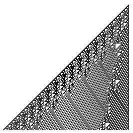
250 iterations of rule 110 are illustrated above.
The mirror image is rule 124, the complement is rule 137, and the mirrored complement is rule 193.
Starting with a single black cell, successive generations are given by interpreting the numbers 1, 6, 28, 104, 496, 1568, 7360, 27520, ... (OEIS A117999) in binary. Omitting trailing zeros (since the right  cells in step
  of the triangle are always 0) gives the sequence 1, 3, 7, 13, 31, 49, 115, 215, 509, 775, 1805, ... (OEIS A006978), which are simply the previous numbers divided by
  , and the corresponding sequence is 1, 11, 111, 1101, 11111, ... (OEIS A070887).
Amazingly, the rule 110 cellular automaton is universal, as first conjectured by Wolfram (1986, pp. 485-557) and subsequently proven by Stephen Wolfram and his assistant Matthew Cook. This important discovery followed a program begun by Wolfram in 1985 to establish universality of rule 110. The main elements of the proof were put in place in 1994, with additional details and corrections continuing for several years (Wolfram 2002, p. 1115; Cook 2004).
In an elementary cellular automaton, a one-dimensional pattern of 0s and 1s evolves according to a simple set of rules. Whether a point in the pattern will be 0 or 1 in the new generation depends on its current value, as well as on those of its two neighbors.

The Rule 110 automaton has the following set of rules:
| Current pattern | 111 | 110 | 101 | 100 | 011 | 010 | 001 | 000 |
|---|---|---|---|---|---|---|---|---|
| New state for center cell | 0 | 1 | 1 | 0 | 1 | 1 | 1 | 0 |
The name "Rule 110" derives from the fact that this rule can be summarized in the binary sequence 01101110; interpreted as a binary number, this corresponds to the decimal value 110.
Formal definition[edit | edit source]
The commonly known 1D binary CA rule 110 is defined as where

- can be finite or infinite
- is a set of two values
- is the neighborhood of size with symmetric radius
- is the local transition function rule


- is the optional boundary usually chosen not to interfere with the quiescent background of all zeros


De Bruijn diagrams[edit | edit source]
Overlap[edit | edit source]

Neighborhoods of adjacent cells are overlapping for cells. There are different overlaps or written in compact form .


Symbolic De Bruijn diagram[edit | edit source]

The De Bruijn diagram has nodes (one for each of the possible overlaps) and links (one for each of the possible neighborhoods).


preimage matrix[edit | edit source]
There are two preimage matrices, one for each of the available cell states.
Rule 110 is a one-dimensional cellular automaton with interesting properties (such as being Turing-complete).
There is a one-dimensional array of cells (on or off). At each time step, the state of each cell changes. In Rule 110, the next state of each cell depends only on itself and its two neighbours, according to the following table:
Left Center Right Center's next state 1 1 1 0 1 1 0 1 1 0 1 1 1 0 0 0 0 1 1 1 0 1 0 1 0 0 1 1 0 0 0 0 (The name "Rule 110" comes from reading the "next state" column: 01101110 is decimal 110.)
In this circuit, create a 512-cell system (q[511:0]), and advance by one time step each clock cycle. The load input indicates the state of the system should be loaded with data[511:0]. Assume the boundaries (q[-1] and q[512]) are both zero (off).
- module top_module(
input clk,
input load,
input [511:0] data,
output [511:0] q
);
always @(posedge clk) begin
if(load)
q <= data;
else
q <= q^{q[510:0],1'b0} | q & ~{1'b0,q[511:1]} ;
end
endmodule 

q <= q^{q[510:0],1'b0} | q & ~{1'b0,q[511:1]} ;
- q= Center
q[510:0],1'b0 =Right
1'b0,q[511:1] = Left


沒有留言:
張貼留言