2021年6月27日 星期日

HDLBits FSM/Lemmings2

HDLBits FSM/Lemmings2 

See also: Lemmings1.

In addition to walking left and right, Lemmings will fall (and presumably go "aaah!") if the ground disappears underneath them.

In addition to walking left and right and changing direction when bumped, when ground=0, the Lemming will fall and say "aaah!". When the ground reappears (ground=1), the Lemming will resume walking in the same direction as before the fall. Being bumped while falling does not affect the walking direction, and being bumped in the same cycle as ground disappears (but not yet falling), or when the ground reappears while still falling, also does not affect the walking direction.

Build a finite state machine that models this behaviour.


該題在上一題的基礎上添加了掉落的狀態fall,輸入信號中多了ground信號,當ground=1時表示在地面上,ground=0時表示在掉落中。輸出信號多了aaah信號,表示掉落狀態時的尖叫聲啊啊啊hhh。這里需要注意的是掉落著陸後的方向問題,題目也明確指出方向與掉落前一致。另外需要注意的是在掉落過程中walk_left/right的狀態輸出均為0。波形圖如下

雖然掉落時不區分方向,輸出只有aaah,但是著陸後的方向與掉落前方向一致,所以這里將掉落狀態分為兩個狀態更為方便,即向左走的時候发生掉落fall_l和向右走的時候发生掉落fall_r狀態。這樣當著陸後直接返回相應的left和right狀態即可。所以fall_l和fall_r狀態之間也不能发生轉換。狀態機描述如下


module top_module(
    input clk,
    input areset,    // Freshly brainwashed Lemmings walk left.
    input bump_left,
    input bump_right,
    input ground,
    output walk_left,
    output walk_right,
    output aaah ); 

    parameter left = 0 ,right = 1 ,fall_l = 2 ,fall_r = 3;
   
    reg[1:0] state, next_state;
    reg[2:0] out;
    
    assign {walk_left, walk_right, aaah} = out;
    //state
    always@(posedge clk or posedge areset) begin
        if(areset)
            state <= left;
        else
            state <= next_state;
    end
    
    //transition
    always@(*)begin
        case(state)
            left:next_state=ground?(bump_left?right:left):fall_l;
            right:next_state=ground?(bump_right?left:right):fall_r;
            fall_l:next_state=ground?left:fall_l;
            fall_r:next_state=ground?right:fall_r;
        endcase
    end
    
    //out
    always@(posedge clk or posedge areset) begin
        if(areset)
            out <= 3'b100;
        else
            case(next_state)
                left:   out <= 3'b100;
                fall_l: out <= 3'b001;
                right:  out <= 3'b010;
                fall_r: out <= 3'b001;
            endcase
    end
endmodule


2021年6月26日 星期六

HDLBits FSM/Lemmings1

 HDLBits FSM/Lemmings1

The game Lemmings involves critters with fairly simple brains. So simple that we are going to model it using a finite state machine.

In the Lemmings' 2D world, Lemmings can be in one of two states: walking left or walking right. It will switch directions if it hits an obstacle. In particular, if a Lemming is bumped on the left, it will walk right. If it's bumped on the right, it will walk left. If it's bumped on both sides at the same time, it will still switch directions.

Implement a Moore state machine with two states, two inputs, and one output that models this behaviour.

Lemmings系列問題是循序漸進的,所以這里第一道題當然是最簡單的。題目表述很明確,Lemmings是2D世界中的遊戲角色,這里只能往左走或往右走,如果在某個方向上遇到障礙就會自動掉頭往另一個方向走,如果沒有遇到障礙就在該方向一直走下去。如果左右都遇到了障礙就在原地不斷掉頭。當然這里的動作都是在時鐘上升沿實現的,要求用Moore狀態機實現。

這里的輸入有clk,areset,bump_left,bump_right,其中bump_left表示左邊遇到障礙,bump_right表示右邊遇到障礙。輸出有walk_left,walk_right,分別表示當前狀態是往左走還是往右走。波形圖如下所示

狀態就兩個,要麽向左走,要麽向右走。


module top_module(
    input clk,
    input areset,    // Freshly brainwashed Lemmings walk left.
    input bump_left,
    input bump_right,
    output walk_left,
    output walk_right); //  
    parameter LEFT=0, RIGHT=1;
    reg state, next_state;
   
    always @(posedge clk, posedge areset) begin
        // State flip-flops with asynchronous reset
        if(areset)begin
           state <= LEFT; 
        end
        else begin
           state <= next_state; 
        end
    end
    
    always@(*) begin
case (state)
LEFT : next_state = bump_left  ? RIGHT : LEFT;
RIGHT: next_state = bump_right ? LEFT : RIGHT;
endcase
    end
    // Output logic
    assign walk_left =  (state==LEFT)?1:0;
    assign walk_right = (state==RIGHT)?1:0;
endmodule

HDLBits FSM/Design a Moore FSM (Exams/ece241 2013 q4)

HDLBits FSM/Design a Moore FSM (Exams/ece241 2013 q4)

題目內容翻譯:

大型水庫可為多個用戶提供服務。為了使水位足夠高,三個傳感器以5英寸的間隔垂直放置。當水位高於最高傳感器(S3)時,輸入流量應為零。當液位低於最低傳感器(S1)時,流量應最大(標稱流量閥和輔助流量閥均打開)。當水位在上下傳感器之間時,流速由兩個因素決定:水位和最後一個傳感器變化之前的水位。每種水位都有一個與之相關的標稱流速,如下表所示。如果傳感器變化表明先前的液位低於當前的液位,則應進行標稱流速。如果先前的水平高於當前水平,則應通過打開輔助流量閥(由ΔFR控制)來增加流量。

繪制水庫控制器的摩爾模型狀態圖。清楚地指出每個狀態的所有狀態轉換和輸出。 FSM的輸入為S1,S2和S3。輸出為FR1,FR2,FR3和ΔFR。

把四個水閥的狀態合並成一個四位二進制,
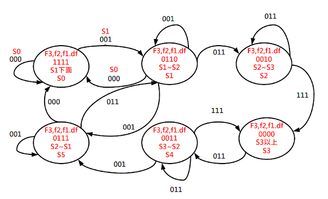
根據題目中的提供的信息,可以得到下面圖中的水閥狀態一共是有S0-S7一共8種,但是S1和S6實際上是不存在的狀態,從狀態跳轉圖也可以很清楚看出來是不穩定的。
最主要的是輔助流量閥ΔFR的值,這里需要注意的是,如果水位從4變到5,即其依舊保持在S2與S3之間,這個時候表示傳感器其實是沒有探測到水位變化的,所以說ΔFR的值是並不會變化的。
具體的水閥開關和狀態跳轉在下圖中給了明確表示,為了避免看起來覆雜,我把每個狀態分開了。雖然S1和S6狀態不存在,但是我還是畫出來方便理解。可以看到他們會自動跳轉到S0和S7。代碼中我也會列出方便理解。
module top_module (
    input clk,
    input reset,
    input [3:1] s,
    output fr3,
    output fr2,
    output fr1,
    output dfr
); 
       parameter S0 = 4'b0000;
    parameter S1 = 4'b0001;
    parameter S2 = 4'b0010;
    parameter S3 = 4'b0011;
    parameter S4 = 4'b0110;
    parameter S5 = 4'b0111;
    parameter S6 = 4'b1110;
    parameter S7 = 4'b1111;
    
    reg [3:0] state,next_state;
    
    always@(*)begin
        case(state)
            S0:next_state<= (s==7)?S0:(s>=3)?S3:(s>=1)?S5:S7;
            S1:next_state<= (s==7)?S1:(s>=3)?S3:(s>=1)?S5:S7;
            S2:next_state<= (s==7)?S0:(s>=3)?S2:(s>=1)?S5:S7;
            S3:next_state<= (s==7)?S0:(s>=3)?S3:(s>=1)?S5:S7;
            S4:next_state<= (s==7)?S0:(s>=3)?S2:(s>=1)?S4:S7;
            S5:next_state<= (s==7)?S0:(s>=3)?S2:(s>=1)?S5:S7;
            S6:next_state<= (s==7)?S0:(s>=3)?S2:(s>=1)?S4:S7;
            S7:next_state<= (s==7)?S0:(s>=3)?S2:(s>=1)?S4:S7;
        endcase
    end
    
    always@(posedge clk)begin
        if(reset)begin
            state <= S7;
        end
        else begin
            state <= next_state;
        end
    end
    
    assign {fr3,fr2,fr1,dfr} = state;

endmodule


另一參考

水位在S1下(S1,S2,S3=0):fr1,fr2,fr3,dfr=1;
水位在S2和S1之間(S1=1,S2,S3=0):fr1, fr2=1;
水位在S3和S2之間(S1,S2=1,S3=0):fr1=1;
水位超過S3(S1,S2,S3=1):fr1,fr2,fr3,dfr=0。
並要求前一時刻的水位高於當前時刻水位時(即放水過程)dfr=1。
本題中使用了6個狀態位,為直觀方便將轉換條件單獨提出。


module top_module (
    input clk,
    input reset,
    input [3:1] s,
    output fr3,
    output fr2,
    output fr1,
    output dfr
); 
    parameter S0 = 4'd0;
    parameter S1 = 4'd1;
    parameter S2 = 4'd2;
    parameter S3 = 4'd3;
    parameter S4 = 4'd4;
    parameter S5 = 4'd5;

    reg [2:0] state_c, state_n;
    wire S02S1, S12S0, S12S2, S22S3, S22S5, S32S4, S42S5, S42S3, S52S0, S52S2;
    always@(posedge clk) begin
        if(reset)
            state_c<=S0;
        else
            state_c <= state_n;
    end
    
    assign S02S1 = s[3:1] == 3'b001 && state_c == S0;
    assign S12S0 = s[3:1] == 3'b000 && state_c == S1;
    assign S12S2 = s[3:1] == 3'b011 && state_c == S1;
    assign S22S3 = s[3:1] == 3'b111 && state_c == S2;
    assign S22S5 = s[3:1] == 3'b001 && state_c == S2;
    assign S32S4 = s[3:1] == 3'b011 && state_c == S3;
    assign S42S5 = s[3:1] == 3'b001 && state_c == S4;
    assign S42S3 = s[3:1] == 3'b111 && state_c == S4;
    assign S52S0 = s[3:1] == 3'b000 && state_c == S5;
    assign S52S2 = s[3:1] == 3'b011 && state_c == S5;
    always@(*) begin
        case(state_c)
            S0:begin
                if(S02S1)
                    state_n = S1;
                else
                    state_n = state_c;
            end
            S1:begin
                if(S12S2)
                    state_n = S2;
                else if(S12S0)
                    state_n = S0;
                else
                    state_n = state_c;
            end            
            S2:begin
                if(S22S3)
                    state_n = S3;
                else if(S22S5)
                    state_n = S5;
                else
                    state_n = state_c;
            end                    
            S3:begin
                if(S32S4)
                    state_n = S4;
                else
                    state_n = state_c;
            end
            S4:begin
                if(S42S5)
                    state_n = S5;
                else if(S42S3)
                    state_n = S3;
                else
                    state_n = state_c;
            end   
            S5:begin
                if(S52S0)
                    state_n = S0;
                else if(S52S2)
                    state_n = S2;
                else
                    state_n = state_c;
            end
        endcase
    end
    // Output logic
    // assign out = (state == ...);
    assign fr3 = state_c == S0;
    assign fr2 = state_c == S0 || state_c == S1 || state_c == S5;
    assign fr1 = state_c == S0 || state_c == S1 || state_c == S2 || state_c==S4 || state_c==S5;
    assign dfr = state_c == S0 || state_c == S4 || state_c == S5;
endmodule

另一參考
module top_module (
    input clk,
    input reset,
    input [3:1] s,
    output reg fr3,
    output reg fr2,
    output reg fr1,
    output reg dfr
); 
parameter A2=0, B1=1, B2=2, C1=3, C2=4, D1=5;
reg [2:0] state, next; // Make sure these are big enough to hold the state encodings.

    // Edge-triggered always block (DFFs) for state flip-flops. Synchronous reset.
always @(posedge clk) begin
if (reset) 
            state <= A2;
else 
            state <= next;
end

    // what should be next state be?
    // Combinational always block: Use blocking assignments.    
always@(*) begin
case (state)
A2: next = s[1] ? B1 : A2;
B1: next = s[2] ? C1 : (s[1] ? B1 : A2);
B2: next = s[2] ? C1 : (s[1] ? B2 : A2);
C1: next = s[3] ? D1 : (s[2] ? C1 : B2);
C2: next = s[3] ? D1 : (s[2] ? C2 : B2);
D1: next = s[3] ? D1 : C2;
default: next = 'x;
endcase
end
    
    
always@(*) begin
case (state)
A2: {fr3, fr2, fr1, dfr} = 4'b1111;
B1: {fr3, fr2, fr1, dfr} = 4'b0110;
B2: {fr3, fr2, fr1, dfr} = 4'b0111;
C1: {fr3, fr2, fr1, dfr} = 4'b0010;
C2: {fr3, fr2, fr1, dfr} = 4'b0011;
D1: {fr3, fr2, fr1, dfr} = 4'b0000;
default: {fr3, fr2, fr1, dfr} = 'x;
endcase
    end
endmodule

HDLBits FSM/Fsm3s

HDLBits FSM/Fsm3s

 See also: State transition logic for this FSM

The following is the state transition table for a Moore state machine with one input, one output, and four states. Implement this state machine. Include a synchronous reset that resets the FSM to state A. (This is the same problem as Fsm3 but with a synchronous reset.)

StateNext stateOutput
in=0in=1
AAB0
BCB0
CAD0
DCB1

module top_module(
    input clk,
    input in,
    input reset,
    output out); //
    
    parameter A=2'd0,B=2'd1,C=2'd2,D=2'd3; 
    reg [1:0] state; // Make sure state and next are big enough to hold the state encodings.
    reg [1:0] next;
    
    // This is a sequential always block
    //非同步 :reset , clk 二者獨立
    //同步 :  僅能依賴 clk  
   // 非同步 always @(posedge clk, posedge areset) begin
   // 同步   always @(posedge clk, posedge reset) begin
    always @(posedge clk) begin
  if (reset) state <= A;
        else state <= next;
end
 // State transition logic
    always@(*) begin
case (state)
A: next = in ? B : A;
B: next = in ? B : C;
C: next = in ? D : A;
D: next = in ? B : C;
endcase
    end
    // Output logic
    // assign out = (state == ...);
    always@(*) begin
   case (state)
A: out = 1'b0;
B: out = 1'b0;
C: out = 1'b0;
D: out = 1'b1;
       endcase
    end  
endmodule

HDLBiots FSM/Fsm3

HDLBiots FSM/Fsm3

See also: State transition logic for this FSM

The following is the state transition table for a Moore state machine with one input, one output, and four states. Implement this state machine. Include an asynchronous reset that resets the FSM to state A.

StateNext stateOutput
in=0in=1
AAB0
BCB0
CAD0
DCB1

module top_module(
    input clk,
    input in,
    input areset,
    output out); //

    parameter A=2'd0,B=2'd1,C=2'd2,D=2'd3; 
    reg [1:0] state; // Make sure state and next are big enough to hold the state encodings.
    reg [1:0] next;
    
    // This is a sequential always block
    always @(posedge clk, posedge areset) begin
if (areset) state <= A;
        else state <= next;
end

 // State transition logic

    always@(*) begin
case (state)
A: next = in ? B : A;
B: next = in ? B : C;
C: next = in ? D : A;
D: next = in ? B : C;
endcase
    end


    // Output logic
    // assign out = (state == ...);

    always@(*) begin
   case (state)
A: out = 1'b0;
B: out = 1'b0;
C: out = 1'b0;
D: out = 1'b1;
       endcase
    end  
endmodule


HDLBits FSM/Fsm3onehot

HDLBits FSM/Fsm3onehot 

The following is the state transition table for a Moore state machine with one input, one output, and four states. Use the following one-hot state encoding: A=4'b0001, B=4'b0010, C=4'b0100, D=4'b1000.

Derive state transition and output logic equations by inspection assuming a one-hot encoding. Implement only the state transition logic and output logic (the combinational logic portion) for this state machine. (The testbench will test with non-one hot inputs to make sure you're not trying to do something more complicated).


StateNext stateOutput
in=0in=1
AAB0
BCB0
CAD0
DCB1

What does "derive equations by inspection" mean?

One-hot state machine encoding guarantees that exactly one state bit is 1. This means that it is possible to determine whether the state machine is in a particular state by examining only one state bit, not all state bits. This leads to simple logic equations for the state transitions by examining the incoming edges for each state in the state transition diagram.

For example, in the above state machine, how can the state machine can reach state A? It must use one of the two incoming edges: "Currently in state A and in=0" or "Currently in state C and in = 0". Due to the one-hot encoding, the logic equation to test for "currently in state A" is simply the state bit for state A. This leads to the final logic equation for the next state of state bit A: next_state[0] = state[0]&(~in) | state[2]&(~in). The one-hot encoding guarantees that at most one clause (product term) will be "active" at a time, so the clauses can just be ORed together.

When an exercise asks for state transition equations "by inspection", use this particular method. The judge will test with non-one-hot inputs to ensure your logic equations follow this method, rather that doing something else (such as resetting the FSM) for illegal (non-one-hot) combinations of the state bits.

Although knowing this algorithm isn't necessary for RTL-level design (the logic synthesizer handles this), it is illustrative of why one-hot FSMs often have simpler logic (at the expense of more state bit storage), and this topic frequently shows up on exams in digital logic courses.

parameter A=4'b0001, B=4'b0010, C=4'b0100, D=4'b1000 ;

// State transition logic: Derive an equation for each state flip-flop.

assign next_state[A] = state[A]&(~in) | state[C]&(~in);
assign next_state[B] = state[A]&(in) | state[B]&(in) | state[D]&(in) ;
assign next_state[C] = state[B]&(~in) | state[D]&(~in);
assign next_state[D] = state[C]&(in) ;

assign next_state[A] = state[A]&(~in) | state[C]&(~in);


module top_module(
    input in,
    input [3:0] state,
    output [3:0] next_state,
    output out); //
    parameter A=4'b0001, B=4'b0010, C=4'b0100, D=4'b1000 ;
    

// State transition logic: Derive an equation for each state flip-flop.
    assign next_state[A] = state[A]&(~in) | state[C]&(~in);
    assign next_state[B] = state[A]&(in) | state[B]&(in) | state[D]&(in) ;
    assign next_state[C] = state[B]&(~in) | state[D]&(~in);
    assign next_state[D] = state[C]&(in) ;
    

// Output logic: 
    assign out = state[D];
endmodule


HDLBits FSM / Fsm3comb

 HDLBits FSM / Fsm3comb

The following is the state transition table for a Moore state machine with one input, one output, and four states. Use the following state encoding: A=2'b00, B=2'b01, C=2'b10, D=2'b11.

Implement only the state transition logic and output logic (the combinational logic portion) for this state machine. Given the current state (state), compute the next_state and output (out) based on the state transition table.

StateNext stateOutput
in=0in=1
AAB0
BCB0
CAD0
DCB1

module top_module(
    input in,
    input [1:0] state,
    output [1:0] next_state,
    output out); //


    parameter A=0, B=1, C=2, D=3;


    always @(*) begin    // This is a combinational always block
        // State transition logic

        case(state)
            A: next_state= in? B:A;
            B: next_state= in? B:C;
            C: next_state= in? D:A;
            D: next_state= in? B:C;
        endcase
    end


    // Output logic
    // assign out = (state == ...);
    always@(*) begin
   case (state)

A: out = 1'b0;
B: out = 1'b0;
                    C: out = 1'b0;
D: out = 1'b1;
endcase
    end
endmodule

HDLBits Simple FSM2S

HDLBits Simple FSM2S

 This is a Moore state machine with two states, two inputs, and one output. Implement this state machine.

This exercise is the same as fsm2, but using synchronous reset.

Fsmjks.png

同步

    always @(posedge clk) begin

 非同步

 always @(posedge clk, posedge areset) begin   

module top_module(
    input clk,
    input reset,    // Synchronous reset to OFF
    input j,
    input k,
    output out); //  
    parameter OFF=0, ON=1; 
    reg state, next_state;
    
    always @(posedge clk) begin
        // State flip-flops with asynchronous reset
        if(reset) state<=OFF;
        else state<=next_state;
    end
    
    always @(*) begin
        case(state)
            OFF: next_state=j?ON:OFF;
            ON:  next_state=k?OFF:ON;
        endcase
    end
    // Output logic
    // assign out = (state == ...);
    always@(*) begin
   case (state)
OFF: out = 1'b0;
ON: out = 1'b1;
endcase
    end  
endmodule

HDLBits Simple FSM2

 HDLBits Simple FSM2 

This is a Moore state machine with two states, two inputs, and one output. Implement this state machine.

This exercise is the same as fsm2s, but using asynchronous reset.

Fsmjk.png


module top_module(
    input clk,
    input areset,    // Asynchronous reset to OFF
    input j,
    input k,
    output out); //  
    parameter OFF=0, ON=1; 
    reg state, next_state;
    
    always @(posedge clk, posedge areset) begin
        // State flip-flops with asynchronous reset
        if(areset) state<=OFF;
        else state<=next_state;
    end
    
    always @(*) begin
        case(state)
            OFF: next_state=j?ON:OFF;
            ON:  next_state=k?OFF:ON;
        endcase
    end
    // Output logic
    // assign out = (state == ...);
    always@(*) begin
   case (state)
OFF: out = 1'b0;
ON: out = 1'b1;
endcase
    end  
endmodule


HDLBits Simple FSM1 / Fsm1s

HDLBits Simple FSM1 / Fsm1s 

This is a Moore state machine with two states, one input, and one output. Implement this state machine. Notice that the reset state is B.

This exercise is the same as fsm1, but using synchronous reset.同步式 reset.

// Note the Verilog-1995 module declaration syntax here:
module top_module(clk, reset, in, out);
    input clk;
    input reset;    // Synchronous reset to state B
    input in;
    output out;//  


    reg out;
    // Fill in state name declarations
    reg present_state, next_state;


    always @(posedge clk) begin
        if (reset) begin  
               // Fill in reset logic
        end else begin
            case (present_state)
                    // Fill in state transition logic
            endcase
            // State flip-flops
            present_state = next_state;   
            case (present_state)
                // Fill in output logic
            endcase
        end
    end


endmodule


與非同步式的差別

同步式
always @(posedge clk) begin    
// State flip-flops with asynchronous reset
     if (reset) 
           state<=B;
        else
           state<=next_state;    
    end


非同步式

always @(posedge clk, posedge areset) begin    
// State flip-flops with asynchronous reset
        if (areset) 
           state<=B;
        else
           state<=next_state;    
    end 


// Note the Verilog-1995 module declaration syntax here:
module top_module(clk, reset, in, out);
    input clk;
    input reset;    // Synchronous reset to state B
    input in;
    output out;//  
    reg out;

    parameter A=0, B=1; 
    reg state, next_state;

    // This is a sequential always block
    always @(posedge clk) begin    
        // State flip-flops with asynchronous reset
    if (reset) 
           state<=B;
        else
           state<=next_state;    
    end

    always @(*) begin    // This is a combinational always block
        // State transition logic
        case(state)
            B: next_state= in? B:A;
            A: next_state= in? A:B;
        endcase
    end

    // Output logic
    // assign out = (state == ...);
    always@(*) begin
   case (state)
A: out = 1'b0;
B: out = 1'b1;
endcase
    end             
endmodule

HDLBits Simple FSM1 / Fsm1

 HDLBits Simple FSM1 / Fsm1

采用三段式的寫法來描述這個簡單的狀態機。三段式狀態機雖然代碼會長一些,但能夠更方便地修改,並更清晰地表達狀態機的跳變與輸出規則。
使用參數來表示每個狀態。


// Give state names and assignments. I'm lazy, so I like to use decimal numbers.
// It doesn't really matter what assignment is used, as long as they're unique.
parameter A=0, B=1;
reg state; // Ensure state and next are big enough to hold the state encoding.
reg next;


    // A finite state machine is usually coded in three parts:
    //  State transition logic
    //  State flip-flops


    //  Output logic
    // It is sometimes possible to combine one or more of these blobs of code
    // together, but be careful: Some blobs are combinational circuits, while some
    // are clocked (DFFs).


三段式分別指
狀態跳轉邏輯
狀態觸发器實現
輸出邏輯


狀態跳轉邏輯,根據輸入信號以及當前狀態確定狀態的次態。
// Combinational always block for state transition logic. Given the current state and inputs,
// what should be next state be?
// Combinational always block: Use blocking assignments.
  always@(*) begin
case (state)
A: next = in ? A : B;
B: next = in ? B : A;
endcase
    end


狀態觸发器實現,在時鐘邊沿實現狀態寄存器的跳變以及狀態覆位
// Edge-triggered always block (DFFs) for state flip-flops. Asynchronous reset.
    

    always @(posedge clk, posedge areset) begin
if (areset) state <= B; // Reset to state B
        else state <= next;  // Otherwise, cause the state to transition
    end


輸出邏輯,根據當前狀態實現輸出
// Combinational output logic. In this problem, an assign statement is the simplest.
// In more complex circuits, a combinational always block may be more suitable.

assign out = (state==B);


module top_module(
    input clk,
    input areset,    // Asynchronous reset to state B
    input in,
    output out);//  


    parameter A=0, B=1; 
    reg state, next_state;


    // This is a sequential always block
    always @(posedge clk, posedge areset) begin    
        // State flip-flops with asynchronous reset
    if (areset) 
           state<=B;
        else
           state<=next_state;    
    end


    always @(*) begin    // This is a combinational always block
        // State transition logic
        case(state)
            B: next_state= in? B:A;
            A: next_state= in? A:B;
        endcase
    end


    // Output logic
    // assign out = (state == ...);
    always@(*) begin
   case (state)
A: out = 1'b0;
B: out = 1'b1;
endcase
    end             
endmodule

2024年4月24日 星期三 Node-Red Dashboard UI Template + AngularJS 參考 AngularJS教學 --2

 2024年4月24日 星期三 Node-Red Dashboard UI Template + AngularJS 參考 AngularJS教學 --2 AngularJS 實例 <!DOCTYPE html> <html> <head> &...