In my previous post, I covered how to upload sketches using NodeMCU, which is firmware written in Lua. I ran into a few problems:
- Uploading big files were prone to error, and it took multiple tries
- Memory! I seemed to not have much
- The callbacks were driving me insane. I decided to not like callback functions for the time being.
In comes Arduino to save the day. There are a lot of useful libraries written for Arduino--libraries for stepper motors and parsing JSON for example. Also, the stepper motors are controlled by Arduino's microcontroller in the end, so it is just simpler to have one language write for both the Wifi Module (ESP) and the microcontroller (Arduino). Last, no upload errors (that weren't my fault).
The first thing I did was blink an LED, because that's simply the first thing you do when you get hardware.
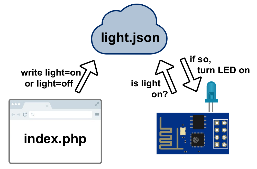
On the client side (the page on my phone), the "Light On" button sends a "On" value to the light.json file. The ESP8266 connects to my home Wifi and reads the light.json file. If it sees an "On" value, it lights up.
If you want to poke around the code, all the code/schematics I describe in this blog post can be found on this project's
GitHub Page.
Parts One: Get Yo Stuff
This project requires the following ingredients:
-
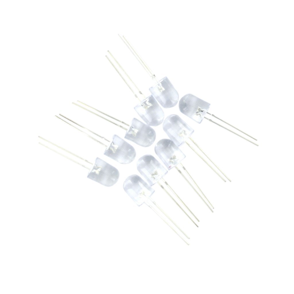
White LED: with forward 3.3V (lower level LEDs tend to confuse the ESP, I'm sure you can use resistors and other magical components to fix this but I didn't look into it much)
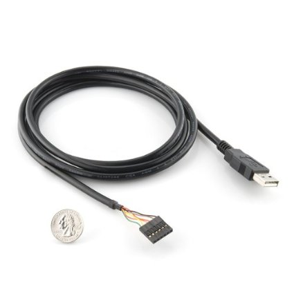
FTDI Cable: You can also use other FTDI tools like FTDI friend
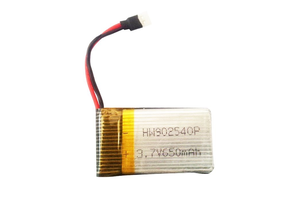
Battery: I used a Lipo (Lithium Ion Polymer) battery because it's small and rechargeable. I actually used
Adafruit's Battery in the video above, but the one I link to on Amazon should work as well (and it comes with a charger).
- You also need essentials like Breadboard and Jumper Wires.
One note. Hehe. I didn't use regulators for this project. The LiPo Battery I'm using is 3.7V and the ESP8266 take 3.3V, so I guess it's not THAT bad. But you should use regulators! At least that's what my friends who electronics tell me. You can find some nice
3.3V Regulators on Adafruit.
Part Two: JSON & PHP
light.json
The light.json file is simple. It either reads {"light":"on"} or {"light":"off"}. That's it. Keep in mind though, it needs to be set to permission 777 so the PHP file can write to it (though 666 works too).
index.php
The index.php file is the public file that writes {"light":"on"} or {"light":"off"} to light.json. Here is the barebones code. There are two links that links you to the current page with a url parameter ?light=on or ?light=off. Based on the url parameter, the PHP writes the appropriate instructions to the JSON file.
<?php
$light = $_GET['light'];
if($light == "on") {
  $file = fopen("light.json", "w") or die("can't open file");
  fwrite($file, '{"light": "on"}');
  fclose($file);
}
else if ($light == "off") {
  $file = fopen("light.json", "w") or die("can't open file");
  fwrite($file, '{"light": "off"}');
  fclose($file);
}
?>

<a href="?light=on">Turn On</a>
<a href="?light=off">Turn Off</a>
<div>
  <?php
    if($light=="on") {
      echo("Turn LED on.");
    }
    else if ($light=="off") {
      echo("Turn LED off.");
    }
    else {
      echo ("Do something.");
    }
  ?>
</div>
I merged this code into my handy
template.html HTML page to start. This page is preloaded with jQuery, Bootstrap (with simple layout preloaded), and Font Awesome. I don't use jQuery or Font Awesome on this particular project. Then I added some styling classes (e.g.
btn-large and styling divs to make things response, pretty, and all that good stuff).
Here's the final code for index.php:
<?php
$light = $_GET['light'];
if($light == "on") {
  $file = fopen("light.json", "w") or die("can't open file");
  fwrite($file, '{"light": "on"}');
  fclose($file);
}
else if ($light == "off") {
  $file = fopen("light.json", "w") or die("can't open file");
  fwrite($file, '{"light": "off"}');
  fclose($file);
}
?>

<html>
  <head>
    <meta charset="utf-8">
    <meta http-equiv="X-UA-Compatible" content="IE=edge">
    <meta name="viewport" content="width=device-width, initial-scale=1">

    <title>LED for ESP8266</title>

    <script src="https://code.jquery.com/jquery-2.1.4.min.js"></script>
    <script src="https://maxcdn.bootstrapcdn.com/bootstrap/3.3.4/js/bootstrap.min.js"></script>
    <link href="https://maxcdn.bootstrapcdn.com/bootstrap/3.3.4/css/bootstrap.min.css" rel="stylesheet">
    <link rel="stylesheet" href="//maxcdn.bootstrapcdn.com/font-awesome/4.3.0/css/font-awesome.min.css">

  </head>
  <body>
    <div class="row" style="margin-top: 20px;">
      <div class="col-md-8 col-md-offset-2">
        <a href="?light=on" class="btn btn-success btn-block btn-lg">Turn On</a>
        <br />
        <a href="?light=off" class="led btn btn-danger btn-block btn-lg">Turn Off</a>
        <br />
        <div class="light-status well" style="margin-top: 5px; text-align:center">
          <?php
            if($light=="on") {
              echo("Turn LED on.");
            }
            else if ($light=="off") {
              echo("Turn LED off.");
            }
            else {
              echo ("Do something.");
            }
          ?>
        </div>
      </div>
    </div>
  </body>
</html>
Part THREE: Hardware: Wire Everything Up
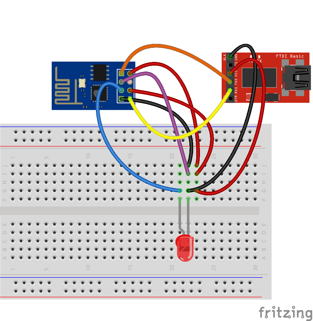
Now that code is written, go ahead and wire things up. To do this I used an FTDI to USB cable. The FTDI cable powers the ESP and connects it to the Serial Terminal. Of course, you can also use FTDI Friend or other FTDI connectors. Here is a diagram of the ESP connected to an LED and an FTDI friend from Sparkfun.
Now, when GPIO0 (the purple wire above) is connected to ground at boot, this tells the ESP to start up in bootloader mode. This is when you can flash the ESP, meaning transfer the Arduino code to the ESP. After the Arduino code is loaded, you'll see a "Done Uploading" status message at the bottom of the ArduinoIDE. Then the code will start running.
If you want to flash another program, then restart the Arduino. You can unplug/replug the USB (which disconnects the Arduino's power source), or you can reset the Arduino by disconnecting the CH_PD (chip powerdown) pin.
If you don't want to restart the device in bootloader mode, simply unplug the GPIO0 cable (the purple wire above).
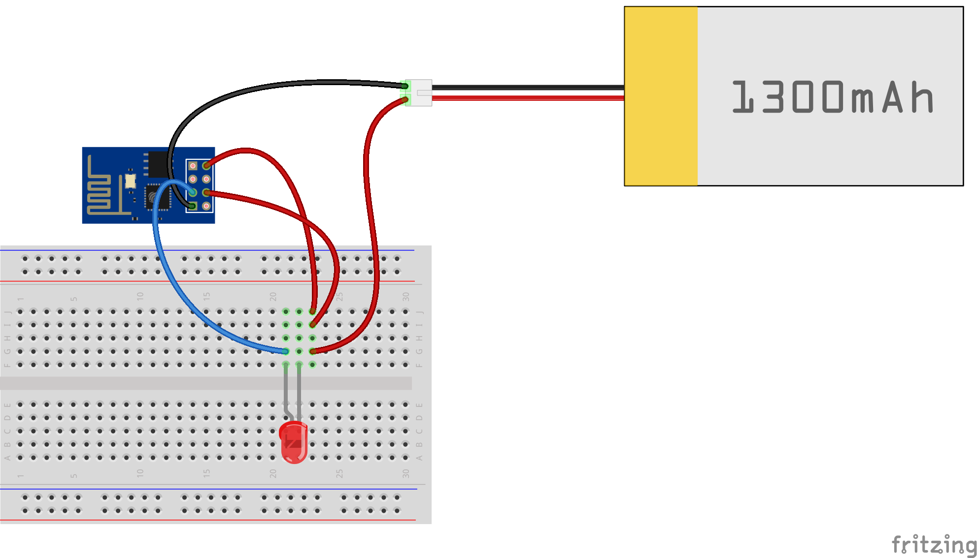
When are you ready to not rely on the USB cable anymore, just unplug everything that connects to the USB. You can also unplug the GPIO to Ground, since you don't need the bootloader mode anymore. You then connect the VCC (power) and GND (ground) to the red (power) and black (ground) of a battery pack that's 3.3-5V. Something like this:
Part Four: Arduino Code
I used the ArduinoIDE to connect with the ESP8266 module. This way, you can flash the ESP just like you would flash an Arduino. It makes developing really easy!
Now, this does not mean you need an Arduino in this example. You are just using the software Arduino publishes which allows you to write program and flash them onto tiny little electronic modules like the many different types of Arduino board and now the ESP8266 module.
1. Install the ESP8266 package in ArduinoIDE
For this, you need Arduino 1.6.4 or higher. You can download the latest software on
Arduino's website. I followed
Adafruit's tutorial for setting up the Arduino IDE. They used their Huzzah breakout, where as I am using the lowly ESP8266-01. The software part is the same, the only difference as far as I can tell is which pins to plug into which socket in the FTDI cable.
After everything is updated, open up Preferences (on Mac it's CMD+, or select from the toolbar Arduino > Preferences). Then enter http://arduino.esp8266.com/package_esp8266com_index.json under "Additional Board Manager's URL" towards the bottom.
Restart Arduino.
Now, in Arduino, you should file under toolbar Tools > Board > Generic ESP8266 Module.
I also followed Adafruit's recommendations on a few other settings:
- CPU Frequency: 80 MHz
- Flash size: 4M
- Upload speed: 115200
- Port: my USB port (this shows up once you plugged everything in)
- Programmer: AVRISP mkll
2. The Arduino Code
Ok, now that ArduinoJson is installed, the we can start doing the fun stuff. I’m going to start off by showing the compiled code. Then I’ll break it down. If you are the type that like to stare at code and learn that way, then just read the following and you’re done! If not, keep going.
Including ArduinoJson.h Library
This basically tells the ESP to ping our light.json file. If the latest value for the key light is on, then turn on the LED. Then rinse and repeat every second. Of course, if the value for the key light is off, then turn off the LED.
Now,
light.json outputs its value using JSON. So we need a parser. Luckily, a bunch of really smart people have already done this. So no need to reinvent the wheel. I used
ArduinoJson. You can find instructions for
installing ArduinoJson library on their wiki.
Then you include this library with #include <ArduinoJson.h> in the file.
The "void setup()" Section
In this section, you set a few basic configurations set to your specific values:
- Your Wifi name and password (the
ssid & password variables)
- Your
light.json URL (the host & path variable)
- Your output pin (we use GPIO2, so
const int pin=2)
In void setup(), you set GPIO2 pin to Output (the O part of GPIO) and I like to flash it on High just to show that it’s turning on.
You also begin a Serial connection using
Serial.begin(115200). This enables you to interact with it using the Serial port, which you can open with the little Magnifying glass in the top left corner of the Arduino IDE. You can also connect to the Serial Terminal using
screen, CoolTerm, or PuTTY. I covered different options in a previous blog
post. When you use
Serial.print("something") or
Serial.println("something"), you should see the results in the Serial Terminal.
Last we start connecting to the internets using Wifi.begin(ssid, password). While the ESP is still connecting, I have it delay and then print a dot. If you are watching the Serial Terminal, you’ll see dots appear until you log in. It’s just a way to see that the little ESP is trying to connect.
#include <ESP8266WiFi.h>
#include <ArduinoJson.h>

const char* ssid     = "";
const char* password = "";

const char* host     = ""; // Your domain, no slashes (ex: www.nyl.io)
String path          = ""; // path to light.json beginning with slash (ex: /esptest/light.json)
const int pin        = 2;

void setup() {
  pinMode(pin, OUTPUT);
  pinMode(pin, HIGH);
  Serial.begin(115200);

  delay(10);
  Serial.print("Connecting to ");
  Serial.println(ssid);

  WiFi.begin(ssid, password);
  int wifi_ctr = 0;
  while (WiFi.status() != WL_CONNECTED) {
    delay(500);
    Serial.print(".");
  }

  Serial.println("WiFi connected");
  Serial.println("IP address: " + WiFi.localIP());
}
The "void loop()" Section
Next we start the void loop() function, which Arduino will run and rerun. Here, we will connect to light.json and print the HTTP response (the info you get from the URL).
The stuff used in client.print(...) is called an HTTP request. This example is contains a very simple request header, you can look through more complex parameters by reading through the XXX.
void loop() {
  Serial.print("connecting to ");
  Serial.println(host);
  WiFiClient client;
  const int httpPort = 80;
  if (!client.connect(host, httpPort)) {
    Serial.println("connection failed");
    return;
  }

  client.print(String("GET ") + path + " HTTP/1.1\r\n" +
               "Host: " + host + "\r\n" +
               "Connection: keep-alive\r\n\r\n");

  delay(500); // wait for server to respond

  // read response
  int dir = 0;
  while(client.available()){
    String line = client.readStringUntil('\r');
    Serial.print(line);
    /////////////////////////////////////////////////////////////////////
    // NOTE: we’ll replace the line above with something to parse the
    // JSON response here!
    /////////////////////////////////////////////////////////////////////
  }
  Serial.print("closing connection. ");
}
Using the two code snippets above, you should see the HTTP response body in the serial, wait a little bit, see it close and re-open the connection, then see the HTTP response body again. Rinse and repeat.
Now that’s all fine and dandy, but we don’t want to see the HTTP response. We want to turn on an LED! So let’s do that now.
Parsing the JSON Response
So when you run that, you should get something like this as a response. You can see the log of the response in your Serial Terminal.
HTTP/1.1 200 OK
Access-Control-Allow-Origin: *
Access-Control-Allow-Headers: X-Requested-With
Content-Type: application/json
Transfer-Encoding: chunked
Content-Disposition: attachment;
Date: Sun, 12 Jul 2015 18:49:27 GMT
Cache-control: private

{"light":"off"}
The first section is the HTTP Response header. It tells you what kind of data you’re getting using application/json, that the webpage is up and running using 200 OK, and other useful, informative things.
I’m going to ignore these useful, informative things.
The next section after the blank line represents the body of the content. On a web browser, this is the stuff that you see.
Ultimately for the blinky LED, we only care about the last line ({"light":"off"}), which tells the ESP8266 what to do with the LED.
I’m sure there are excellent libraries out there to parse this thing, but I wrote something quick and dirty to apply to values I know will appear in my JSON file. Basically, I will tell the code to ignore everything past the first empty line. Then skip the line after that (the blank line), then read the line after that (the JSON data).
If you have a data response with a different structure, this may not work for you. Ok. You’ve been warned. Now let’s continue.
Warning: crazy-silly-but-it-works hack up ahead.
What I do is introduce a variable name section. Using this, I keep track of what section of the HTTP response I'm reading.
The program then reads the HTTP response line by line. Each line is represented by the variable line in the while loop. The default value is section = "header"since the HTTP Response begins with header.
It then doesn’t change until it reaches an empty line. When it reach an empty line if (line=="\n") then the program sets section="json" since the next line will be the JSON line we care about.
We parse the JSON line next, and store the JSON into a json_parsed variable. You can read this in the section after the comments // Parse JSON.
After this, we turn the LED on or off depending on the result. We use the strcmp function (short for string comparison). strcmp(json_parsed["light"], "on") == 0), meaning if the the key light is set to on, then we turn on the LED. We do this using digitalWrite(pin, HIGH) line where the variable pin is the GPIO number we set in the beginning of the file.
Final Arduino Code
#include <ESP8266WiFi.h>
#include <ArduinoJson.h>

const char* ssid     = "";
const char* password = "";

const char* host     = ""; // Your domain
String path          = "/path/to/light.json";
const int pin        = 2;

void setup() {
  pinMode(pin, OUTPUT);
  pinMode(pin, HIGH);
  Serial.begin(115200);

  delay(10);
  Serial.print("Connecting to ");
  Serial.println(ssid);

  WiFi.begin(ssid, password);
  int wifi_ctr = 0;
  while (WiFi.status() != WL_CONNECTED) {
    delay(500);
    Serial.print(".");
  }

  Serial.println("WiFi connected");
  Serial.println("IP address: " + WiFi.localIP());
}

void loop() {
  Serial.print("connecting to ");
  Serial.println(host);
  WiFiClient client;
  const int httpPort = 80;
  if (!client.connect(host, httpPort)) {
    Serial.println("connection failed");
    return;
  }

  client.print(String("GET ") + path + " HTTP/1.1\r\n" +
               "Host: " + host + "\r\n" +
               "Connection: keep-alive\r\n\r\n");

  delay(500); // wait for server to respond

  // read response
  String section="header";
  while(client.available()){
    String line = client.readStringUntil('\r');
    // Serial.print(line);
    // we’ll parse the HTML body here
    if (section=="header") { // headers..
      Serial.print(".");
      if (line=="\n") { // skips the empty space at the beginning
        section="json";
      }
    }
    else if (section=="json") {  // print the good stuff
      section="ignore";
      String result = line.substring(1);

      // Parse JSON
      int size = result.length() + 1;
      char json[size];
      result.toCharArray(json, size);
      StaticJsonBuffer<200> jsonBuffer;
      JsonObject& json_parsed = jsonBuffer.parseObject(json);
      if (!json_parsed.success())
      {
        Serial.println("parseObject() failed");
        return;
      }

      // Make the decision to turn off or on the LED
      if (strcmp(json_parsed["light"], "on") == 0) {
        digitalWrite(pin, HIGH);
        Serial.println("LED ON");
      }
      else {
        digitalWrite(pin, LOW);
        Serial.println("led off");
      }
    }
  }
  Serial.print("closing connection. ");
}
Part Five? Next Steps
The next thing I want to do is connect this whole contraption to a stepper motor. So rather than an LED blinking on and off, the ESP can make a motor turn.
I want to have a bunch of little ESPs around the house connected to different motors that can do different things. I mean, a lot of things require turning action: opening window blinds, turning a key, opening a door. My next step is to get a basic motor example working, then we’ll connect the motors to various household components and start robotifying my apartment.