2018年2月28日 星期三

Shift Register 74HC595 Arduino Library

The Shift Register 74HC595 Arduino Library makes the use of shift registers much easier.

It basically allows you to set single pins of your shift register either high or low, instead of shifting out complicated created bytes. So you can simply increase the number of output pins on your microcontroller without much more work. Source code on GitHub


Get started!


Download the library and install it. Connect the shift register to your Microcontroller as shown in Fig. 1.


Open up a new project in the Arduino IDE and import the library with the following code: 

#include <ShiftRegister74HC595.h>


Create an instance of the ShiftRegister74HC595 class like so:

int numberOfShiftRegisters = 1; // number of shift registers attached in series
int serialDataPin = 0; // DS
int clockPin = 1; // SHCP
int latchPin = 2; // STCP
ShiftRegister74HC595 sr (numberOfShiftRegisters, serialDataPin, clockPin, latchPin); 


If you want to use multiple shift registers in series, connect them as shown in Fig. 2.


You can create multiple instances of the shift register class if necessary. In fact this makes sense if you want to use multiple shift registers parallel and not in series.


Insert the normal setup and loop function.


Congratulations! Now you have additional output pins (Fig. 3 - series resistors are left out for clarify reasons). You can access them with a bunch of methods:

// sets a specific pin of your shift register on high
int pin = 0;
sr.set(pin, HIGH); // equivalent to sr.set(pin, 1);

// sets all pins either on high ...
sr.setAllHigh();
// ... or low
sr.setAllLow();

// sets all pins at once (pin 0 low, pin 1 high, ...)
uint8_t pinValues[] = { B10101010 };
sr.setAll(pinValues); 

// set multiple pins at once when using two shift registers in series
uint8_t pinValues[] = { B00011000, B10101010 };
sr.setAll(pinValues); 


You can also read the current state of a pin:

int pin = 0; 
uint8_t state = sr.get(pin); // 0 = LOW, 1 = HIGH


An example of using the library can be found here.


That's it from me! Feel free to contact me if you have any questions or want to give feedback.

List of all functions


ShiftRegister74HC595(int numberOfShiftRegisters, int serialDataPin, int clockPin, int latchPin);
void setAll(uint8_t * digitalValues);
uint8_t * getAll(); 
void set(int pin, uint8_t value);
void setAllLow();
void setAllHigh(); 
uint8_t get(int pin);


===============測試後 24bit LED ===============

/*
  ShiftRegister74HC595.h - Library for easy control of the 74HC595 shift register.
  Created by Timo Denk (www.simsso.de), Nov 2014.
  Additional information are available on http://shiftregister.simsso.de/
  Released into the public domain.

// sets a specific pin of your shift register on high
int pin = 0;
sr.set(pin, HIGH); // equivalent to sr.set(pin, 1);

// sets all pins either on high ...
sr.setAllHigh();
// ... or low
sr.setAllLow();

// sets all pins at once (pin 0 low, pin 1 high, ...)
uint8_t pinValues[] = { B10101010 };
sr.setAll(pinValues); 

// set multiple pins at once when using two shift registers in series
uint8_t pinValues[] = { B00011000, B10101010 };
sr.setAll(pinValues); 


You can also read the current state of a pin:

int pin = 0; 
uint8_t state = sr.get(pin); // 0 = LOW, 1 = HIGH


*/

// 接 74HC595 的第 12 支接腳
//int latchPin = 5;
// 接 74HC595 的第 11 支接腳
//int clockPin = 4;
// 接 74HC595 的第 14 支接腳
//int dataPin = 16;


#include <ShiftRegister74HC595.h>
// create shift register object (number of shift registers, data pin, clock pin, latch pin)
ShiftRegister74HC595 sr (3, 16, 4, 5); 

void setup() { 
}

void loop() {

  sr.setAllHigh(); // set all pins HIGH
  delay(500);
  
  sr.setAllLow(); // set all pins LOW
  delay(500); 
  
  
  for (int i = 0; i < 23; i++) {
    
    sr.set(i, HIGH); // set single pin HIGH
    delay(250); 
  }
  
  
  // set all pins at once
  byte d1=0x3c;
  byte d2=0xaa;
  byte d3=0x55;
  
  uint8_t pinValues[] = { d1, d2 , d3 };
  sr.setAll(pinValues); 
  delay(10000);

  byte d4=0xc3;
  byte d5=0x55;
  byte d6=0xaa;
  uint8_t pinValues1[] = { d4, d5 , d6 };
  sr.setAll(pinValues1); 
  delay(10000);
  
  
  // read pin (zero based)
  uint8_t stateOfPin5 = sr.get(5);
  uint8_t stateOfPin23 = sr.get(23);
  
  
}


ESP8266 example for a web server turning a lef off and on.

源自於 http://labalec.fr/erwan/?p=1678

Last ESP8266 example for the day (credit goes here) : a web server turning a lef off and on.

#include <ESP8266WiFi.h>
 
const char* ssid = "livebox0";
const char* password = "password";
 
int ledPin = 2; // GPIO2
WiFiServer server(80);
 
void setup() {
  Serial.begin(115200);
  delay(10);
 
  pinMode(ledPin, OUTPUT);
  digitalWrite(ledPin, LOW);
 
  // Connect to WiFi network
  Serial.println();
  Serial.println();
  Serial.print("Connecting to ");
  Serial.println(ssid);
 
  WiFi.begin(ssid, password);
 
  while (WiFi.status() != WL_CONNECTED) {
    delay(500);
    Serial.print(".");
  }
  Serial.println("");
  Serial.println("WiFi connected");
 
  // Start the server
  server.begin();
  Serial.println("Server started");
 
  // Print the IP address
  Serial.print("Use this URL to connect: ");
  Serial.print("http://");
  Serial.print(WiFi.localIP());
  Serial.println("/");
 
}
 
void loop() {
  // Check if a client has connected
  WiFiClient client = server.available();
  if (!client) {
    return;
  }
 
  // Wait until the client sends some data
  Serial.println("new client");
  while(!client.available()){
    delay(1);
  }
 
  // Read the first line of the request
  String request = client.readStringUntil('\r');
  Serial.println(request);
  client.flush();
 
  // Match the request
 
  int value = LOW;
  if (request.indexOf("/LED=ON") != -1)  {
    digitalWrite(ledPin, HIGH);
    value = HIGH;
  }
  if (request.indexOf("/LED=OFF") != -1)  {
    digitalWrite(ledPin, LOW);
    value = LOW;
  }
 
// Set ledPin according to the request
//digitalWrite(ledPin, value);
 
  // Return the response
  client.println("HTTP/1.1 200 OK");
  client.println("Content-Type: text/html");
  client.println(""); //  do not forget this one
  client.println("<!DOCTYPE HTML>");
  client.println("<html>");
 
  client.print("Led pin is now: ");
 
  if(value == HIGH) {
    client.print("On");
  } else {
    client.print("Off");
  }
  client.println("<br><br>");
  client.println("Click <a href=\"/LED=ON\">here</a> turn the LED on pin 2 ON<br>");
  client.println("Click <a href=\"/LED=OFF\">here</a> turn the LED on pin 2 OFF<br>");
  client.println("</html>");
 
  delay(1);
  Serial.println("Client disonnected");
  Serial.println("");
 
}

2018年2月27日 星期二

Switches, Debouncing and the Arduino

源自於
https://core-electronics.com.au/tutorials/switch-debouncing-with-arduino.html

Switches, Debouncing and the Arduino

When we boil it down, everyday interactions with electronics are usually limited to controlling stuff with switches. Whether it be turning on the lights, switching on your laptop or turning on the kettle, all examples of how a physical switch works to control electrical current flow.
Today we are going to look at the different switch types we can get, the specifications of these switches, the schematic symbols and jargon we hear when working with switches and then we will look at the real-world applications of switches and problems we encounter in making circuits that use switches. Especially when interfacing with the Arduino!
As we said before, a switch is a mechanical device that controls current flow in a circuit. Switches have physical states they can be in, and these states are simply open and closed (Off or on, note that order). For example, say you walk into a dark room, you would say the reason the lights are off is cause the switch is off. You would be right too. However, electrically speaking, the switch has been toggled into an open state, meaning it has physically opened the circuit and current cannot flow through the light while the switch is in that state. If we wanted to interface with that circuit, we could physically change the state of the circuit by flicking the switch on, which closes the switch and allows the current to flow through it.


POLES AND THROWS

schematic-switch-symbol-labelled
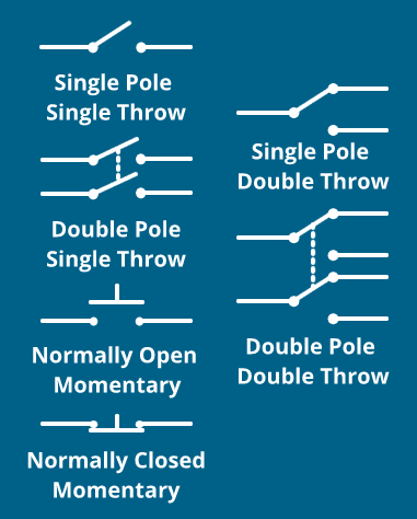
You can tell a bit about a switch by just looking at it, especially the number of connections the switch has. Even for a complete newbie to electronics, these connections are straightforward. That is until we get switches with more than just two connections. Understanding the number of poles and throws a switch has will go far, let's cover that.
The number of poles a switch has refers to the total number of circuits the switch can control. So, for our simple light switch example above, that would be a single pole switch.
The number of throws a switch has is indicative of the number of positions each pole of a switch can be in. Again, for our light switch we tend to think of it as a Single Pole Single Throw switch.
As far as poles and throws go, it is easy to understand.
So, to recap:
Switches are physical components that typically have two states.
Those ‘typical’ button states are open & closed.
They could have any number of poles and throws; these relate how many circuits they can control and how many positions the switch can be in.

A SWITCHES NORMAL STATE

Untoggled switches are said to be in their normal state. Take a look at the schematic symbols above to see how the schematics represent the 'normal' state of a switch. The normal state can be either open or closed, and the terms we use to identify this state are Normally Open and Normally Closed. Some colloquialisms surrounding these terms are Push to Make (normally open, NO) switches and push to break (Normally closed, NC) switches. It is important that we understand that the state of a switch is not necessarily the same in every case, incorrectly connecting a switch might lead to a dangerous short circuit!
Usually, a schematic will indicate the required normal state of a switch, notice the difference between the NO and NC switches in the diagram above!

MOMENTARY & MAINTAINED SWITCHES

In the simple light example, above, the switch was what’s called a maintained switch. A maintained switch will remain in its current state until toggled out of that state. Think of the power button on your computer, the pedestal fan in your room all those things that will stay on once you press the button. These are all different examples of maintained switches.
The other variety of switch we see is a momentary switch, intuitively enough it will only be toggled on momentarily when pressed. This kind of switch is on your keyboard! You press a key, and it is only registering you pressing that letter once. Obviously, there's a bit more behind a keyboard, but it is an excellent example of a momentary switch for our purposes.
Then we have a different category of push-buttons all together, and they are latching switches. This switch looks just like a standard momentary push button, but they can latch into a toggled state, making them more alike a maintained switch.

BOUNCING & DEBOUNCING SWITCHES

oscilloscope-reading-switch-bounce
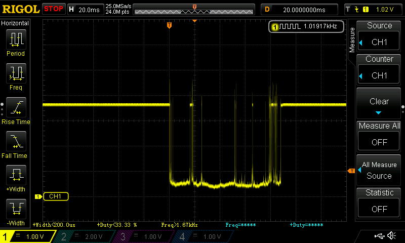
When it comes to the world of digital electronics, work with physical states such as on and off is perfect. In practice, we tend to see that it never works out quite so perfectly, however. Switches are no exception to this exception either; I am referring to bouncing. We would like to think a switch toggle perfectly goes from an off state to an on state, a perfect square wave, but it never does and rarely is.
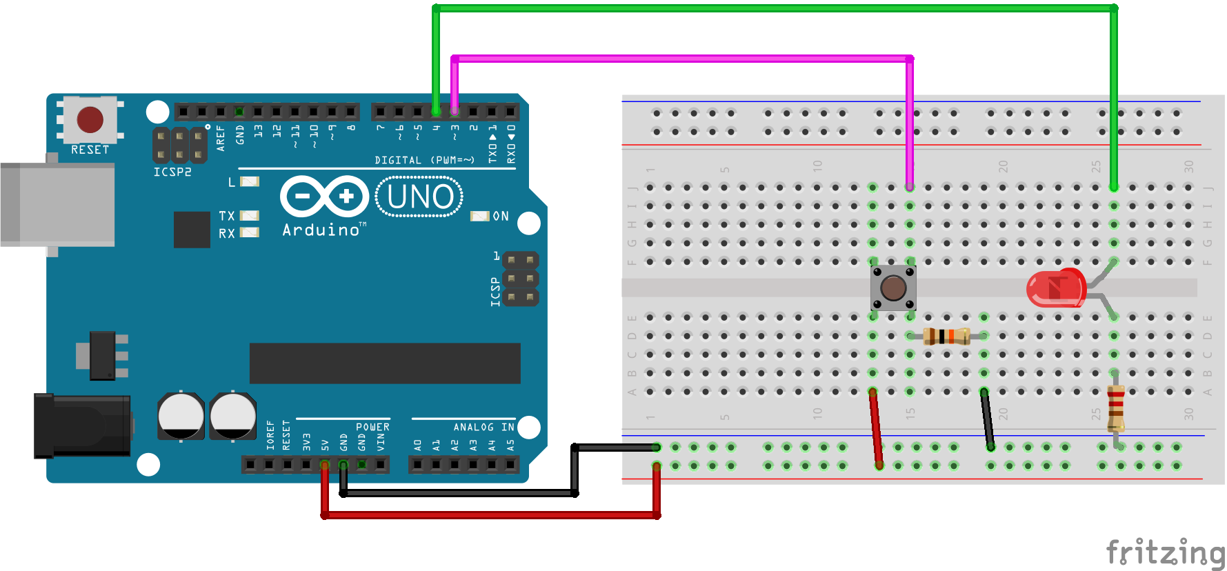
Bouncing is the effect of the mechanical contacts of a switch ‘bouncing’ in between the on/off state when toggled. Bounce can cause all sorts of issues when we are connecting it to any load, let alone a microcontroller. Why so? Well, a Microcontroller can be operating at millions of cycles per second, and these bounce frequencies are occurring right inside of that time domain. The input might try to read your switch’s state and instead of seeing a single, rising edge, from 0-5v; it sees multiple rising and falling edges when you press the button.
If we wanted to combat the bounce associated with a switch, we have hardware or software debounce solution we can implement. We will look at a simple software implementation of debouncing.

MANAGE DEBOUNCING IN THE SKETCH

The general idea behind a software debounce is to write a small snippet of code that works to ignore/bypass the bounce’s noise. Ideally, we would debounce the switch without having any effect on the speed or execution of our program. Unfortunately, that is not possible without some extra hardware, and that just wouldn’t be the software solution we need, would it!?
What we can do, is use a simpler method of polling our buttons state throughout our loop function. If it has changed for a period greater than the expected debounce time we will trigger the action we desire. There are a few other methods we could use, and they are certainly interesting (I’d even call a few of the ways I have seen ingenious), but they are on my list for future tutorials. For now, the polling method will work perfectly fine.

frizting-sketch-debounce-setupTHE SETUP

If you are looking for a wide variety of nifty switches for your next project, be sure to check out the range from Sparkfun. All we will need for our simple debounce example is:
If you do not have the other LED/Resistor lying around, you can use the internal resistor/LED of the Arduino Uno board; you will just need to change the led Pin in the sketch below to pin 13. That is where the onboard LED connects to the AT mega chip!

THE CODE

const int buttonPin = 3;  //This is the buttons read pin
const int ledPin = 4;    // This is the LED output pin

int ledState = HIGH;      //Variable for current LED state
int buttonState;          //Variable for current button reading
int lastButtonState = LOW;//Variable for last know button reading

unsigned long lastDebounceTime = 0; //last time the pin was toggled, used to keep track of time
unsigned long debounceDelay = 50;   //the debounce time which user sets prior to run

void setup() {
  pinMode(buttonPin, INPUT);
  pinMode(ledPin, OUTPUT);
  digitalWrite(ledPin, ledState);
}

void loop() {
  //read the button pin, if pressed will be high, if not pressed will be low
  int reading = digitalRead(buttonPin);
  //in the case that the reading is not equal to the last state set the last debounce time to current millis time
  if (reading != lastButtonState)  {
    lastDebounceTime = millis();
  }
  //check the difference between current time and last registered button press time, if it's greater than user defined delay then change the LED state as it's not a bounce
  if ((millis()-lastDebounceTime) > debounceDelay) {
    if (reading != buttonState) {
      buttonState = reading;
    if (buttonState == HIGH) {
      ledState = !ledState;
      }
    }
  }
  //set the LED
  digitalWrite(ledPin, ledState);

  //save the reading. next time through the loop the state of the reading will be known as the lastButtonState
  lastButtonState = reading;
}

So set up the circuit, upload the code. The effects of this setup should effectively negate the bouncing we experience from the push button. If there is still bouncing occurring you can change the value for the debounce delay (just before the setup function in your sketch). I hope you've enjoyed our explanation of switch debouncing with the Arduino! If you have anything to add, feel free to start the discussion below!

MQTT Explorer 與 Node-Red 介面的實驗

 MQTT Explorer 與 Node-Red 介面的實驗 MQTT EXplorer 與 Node-Red介面的設定 (1) 設定  MQTT EXplorer Client    (2)        Node-Red LED ON  --> MQTT Explor...