http://www.electronicwings.com/nodemcu/nodemcu-spi-with-arduino-ide
NodeMCU SPI with Arduino IDE
Introduction
The Serial Peripheral Interface (SPI) is a bus interface connection protocol originally started by Motorola Corp.
- SPI Interface uses four wires for communication. Hence it is also known as four wire serial communication protocol.
- SPI is a full duplex master-slave communication protocol. This means that only a single master and a single slave can communicate on the interface bus at the same time.
- SPI enabled devices work in two basic modes of SPI operation i.e. SPI Master Mode and SPI Slave Mode.
- Master Device is responsible for initiation of communication. Master Device generates Serial Clock for synchronous data transfer. Master Device can handle multiple slave devices on the bus by selecting them one by one.
NodeMCU based ESP8266 has Hardware SPI with four pins available for SPI communication. With this SPI interface, we can connect any SPI enabled device with NodeMCU and make communication possible with it.
ESP8266 has SPI pins (SD1, CMD, SD0, CLK) which are exclusively used for Quad-SPI communication with flash memory on ESP-12E, hence, they can’t be used for SPI applications. We can use Hardware SPI interface for user end applications.
Below figure shows Quad SPI interface pins that are internally used for flash. It consists quad i/o (4-bit data bus) i.e. four (SDIO_DATA0 – SDIO_DATA3) bidirectional (i/p and o/p) data signals with synchronize clock (SDIO_CLK) and chip select pin (SDIO_CMD). It is mostly used to get more bandwidth/throughput than dual i/o (2-bit data bus) interface.
NodeMCU SPI Pins
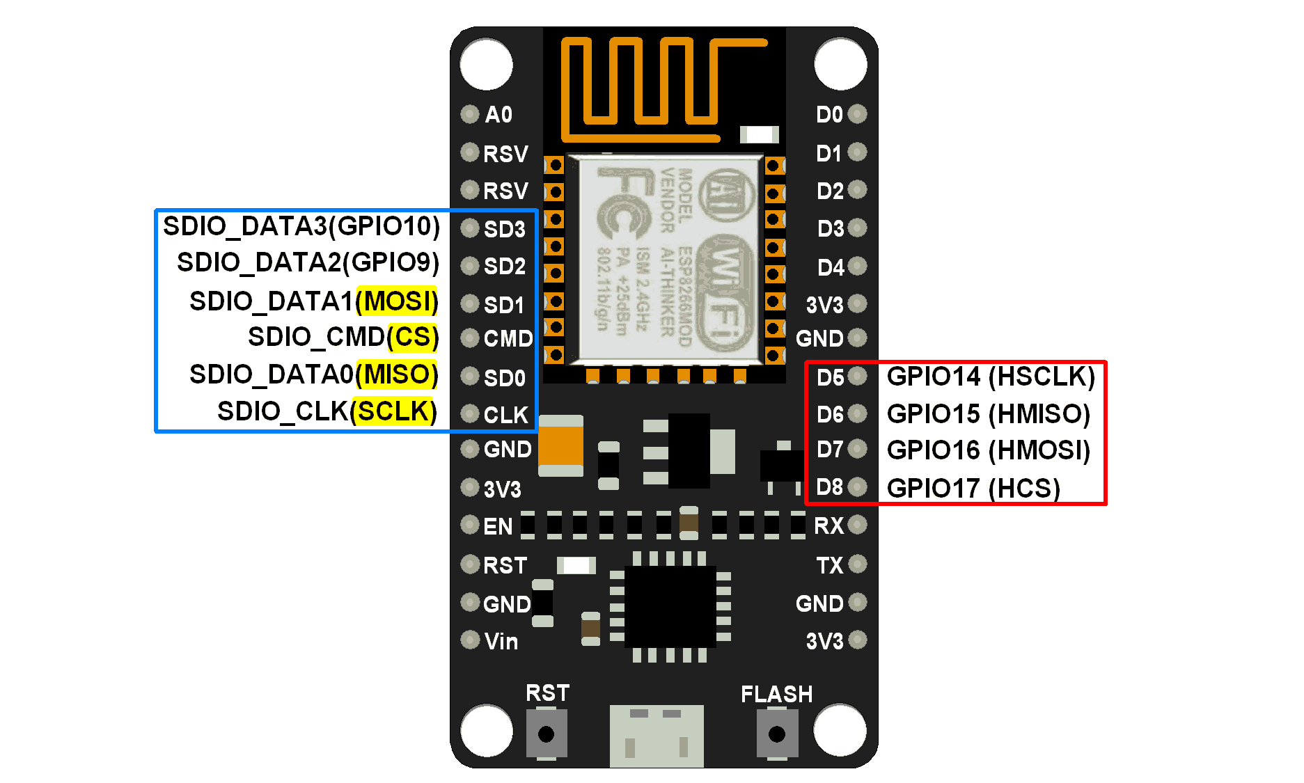
NodeMCU SPI Pins
MISO (Master In Slave Out)
Master receives data and slave transmits data through this pin.
MOSI (Master Out Slave In)
Master transmits data and slave receives data through this pin.
SCLK (Serial Clock)
Master generates this clock for the communication, which is used by slave.
Only master can initiate serial clock.
CS (Chip Select)
Master can select slave device through this pin to start communication with it.
Example
Let’s write Arduino sketch of SPI communication for NodeMCU. Here NodeMCU is acting as master device and we are using Arduino uno as slave device.
In this example, we are sending “Hello Slave” string with ‘\n’ as ending of string from NodeMCU Master device. Slave device receives this string and prints it on serial monitor.
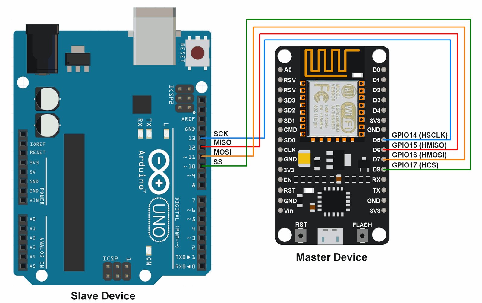
NodeMCU Arduino SPI Interfacing Diagram
Arduino sketch for NodeMCU Master SPI
#include<SPI.h>

char buff[]="Hello Slave\n";

void setup() {
 Serial.begin(9600); /* begin serial with 9600 baud */
 SPI.begin();  /* begin SPI */
}

void loop() {
 for(inti=0; i<sizeof buff; i++)  /* transfer buff data per second */
  SPI.transfer(buff[i]);
 delay(1000);
}
Arduino Sketch for Arduino Uno slave SPI
#include <SPI.h>

char buff [100];
volatile byte index;
volatile bool receivedone;  /* use reception complete flag */

void setup (void)
{
  Serial.begin (9600);
  SPCR |= bit(SPE);         /* Enable SPI */
  pinMode(MISO, OUTPUT);    /* Make MISO pin as OUTPUT */
  index = 0;
  receivedone = false;
  SPI.attachInterrupt();    /* Attach SPI interrupt */
}

void loop (void)
{
  if (receivedone)          /* Check and print received buffer if any */
  {
    buff[index] = 0;
    Serial.println(buff);
    index = 0;
    receivedone = false;
  }
}

// SPI interrupt routine
ISR (SPI_STC_vect)
{
  uint8_t oldsrg = SREG;
  cli();
  char c = SPDR;
  if (index <sizeof buff)
  {
    buff [index++] = c;
    if (c == '\n'){     /* Check for newline character as end of msg */
     receivedone = true;
    }
  }
  SREG = oldsrg;
}
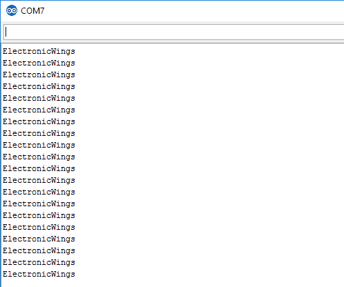
Slave Output Window
This output is received at slave device which is transmitted from master device.
Supporting Files
Source Code
- Arduino Sketch for NodeMCU SPI Master Download 291
Attached File
- ESP8266 Datasheet Download 262


沒有留言:
張貼留言