NodeMCU
Post Time: 2017-05-03 18:05:35 Category: NodeMCU IoT Kit
- What is NodeMCU
- Features
- Specifications
- Pin Definition
- Hardware Resource
- Getting Started with the Osoyoo NodeMCU Kit
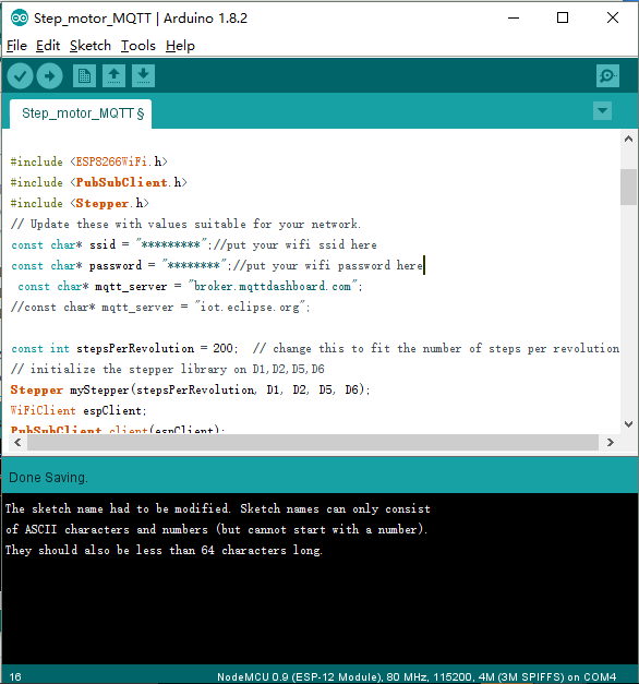
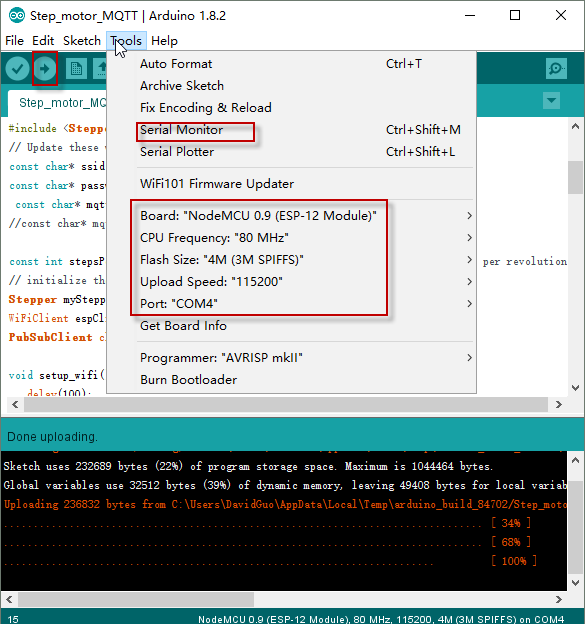
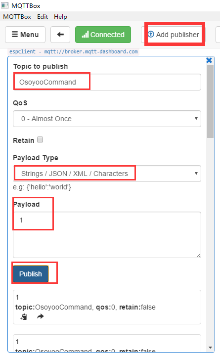
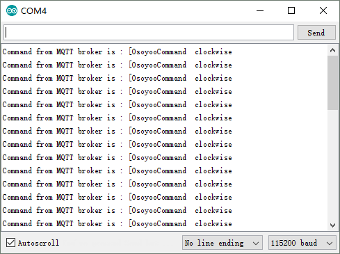
- Tutorial and Sample Projects(Arduino IDE)
- FAQ
- Reference
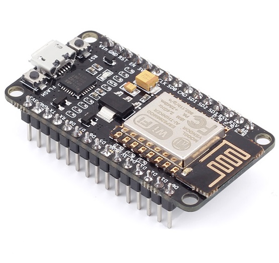
What is NodeMCU?
The NodeMCU development board is a powerful solution to program microcontrollers and be part of the
Internet of Things (IoT). The NodeMCU development board, based on ESP8266EX, is a cute module with
a microcontroller, integrated Wi-Fi receiver, and transmitter. NodeMCU supports several programing languages;
hence, it is very easy to upload programs from any computer over a micro-USB port. I have been playing with the
NodeMCU for quite a while now and, I have to say, it is a lot more fun than the other available IoT modules.
When it comes to prototyping — just another perfect, relatively cheap, easy-to-learn, and user-friendly
minuscule magic module!
Features
- Open-source,Interactive,Programmable,Low cost,Simple,Smart,WI-FI enabled
- Deep sleep power <10uA, Power down leakage current < 5uA
- Wake up and transmit packets in < 2ms
- Standby power consumption of < 1.0mW
- Compatible with Arduino IDE
- Easy to access wireless router
- Based on Lua 5.1.4 (without debug, os module.)
- Event-Drive programming preferred.
- Build-in json, file, timer, pwm, i2c, spi, 1-wire, net, mqtt, coap, gpio, wifi, adc, uart and system api.
- GPIO pin re-mapped, use the index to access gpio, i2c, pwm.
- Both Floating Point and Integer versions of the firmware can be built.
Specifications
| Categories | Items | Parameters |
|---|---|---|
| WiFi | Standard | CCC/FCC/CE/TELEC/SRRC |
| Protocols | 802.11 b/g/n | |
| Frequency Range | 2.4G~2.5G (2400M~2483.5M) | |
| Hardware | MCU | Xtensa L106 |
| RAM | 50K | |
| Flash | 4MB | |
| Peripheral Interface | UART/SDIO/SPI/I2C/I2S/IR Remote Control | |
| GPIO/PWM | ||
| Power Supply | 4.5V~9V(10VMAX),Support USB power supply | |
| Operating Voltage | 3.0~3.6V | |
| Operating Current | Average: 80mA(200mA MAX) | |
| Standby Current | <200uA | |
| Transmission Rate | 110-460800bps | |
| Port Driving Capability | 15mA | |
| Operating Temperature Range | -40℃~+125℃ | |
| Storage Temperature Range | -40℃~+125℃ | |
| Board Size | 48mm x 26mm | |
| Weight | ~7g | |
| Software | Wi-Fi Mode | Station/SoftAP/SoftAP+Station |
| Security | WPA/WPA2 | |
| Encryption | WEP/TKIP/AES | |
| Firmware Upgrade |
UART Download/OTA (via network)
Download and Write Firmware via Host
| |
| SoftwareDevelopment |
Supports Cloud Server Development/
SDK for Custom Firmware Development
| |
| Network Protocols | IPv4,TCP/UDP/HTTP/FTP | |
| User Configuration | AT Instruction Set,Cloud Server,Android/iOS App |
Pin Definition

Note:D0(GPIO16) can only be used as GPIO read/write,no interrupt supported no pwm/i2c/ow
supported.
You can see the new GPIO map as below:
| IO index | ESP8266 pin | IO index | ESP8266 pin |
|---|---|---|---|
| 0 [*] | GPIO16 | 7 | GPIO13 |
| 1 | GPIO4 | 8 | GPIO15 |
| 2 | GPIO5 | 9 | GPIO3 |
| 3 | GPIO0 | 10 | GPIO1 |
| 4 | GPIO2 | 11 | GPIO9 |
| 5 | GPIO14 | 12 | GPIO10 |
| 6 | GPIO12 |
Micro USB port - it use for upload the program and update firmware,you can also charge the battery
Reset button - to have a reset
Flash button - it use for update the firmware
Reset button - to have a reset
Flash button - it use for update the firmware
Hardware Resource
The NodeMCU is a fully open–source hardware,you can get more informations at below links:
hardware Resource: https://github.com/nodemcu/nodemcu-devkit
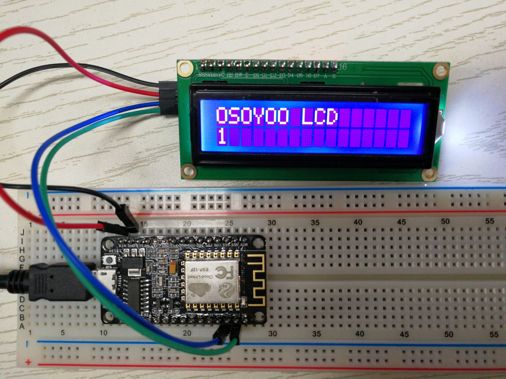
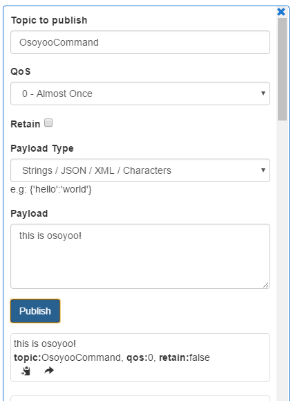
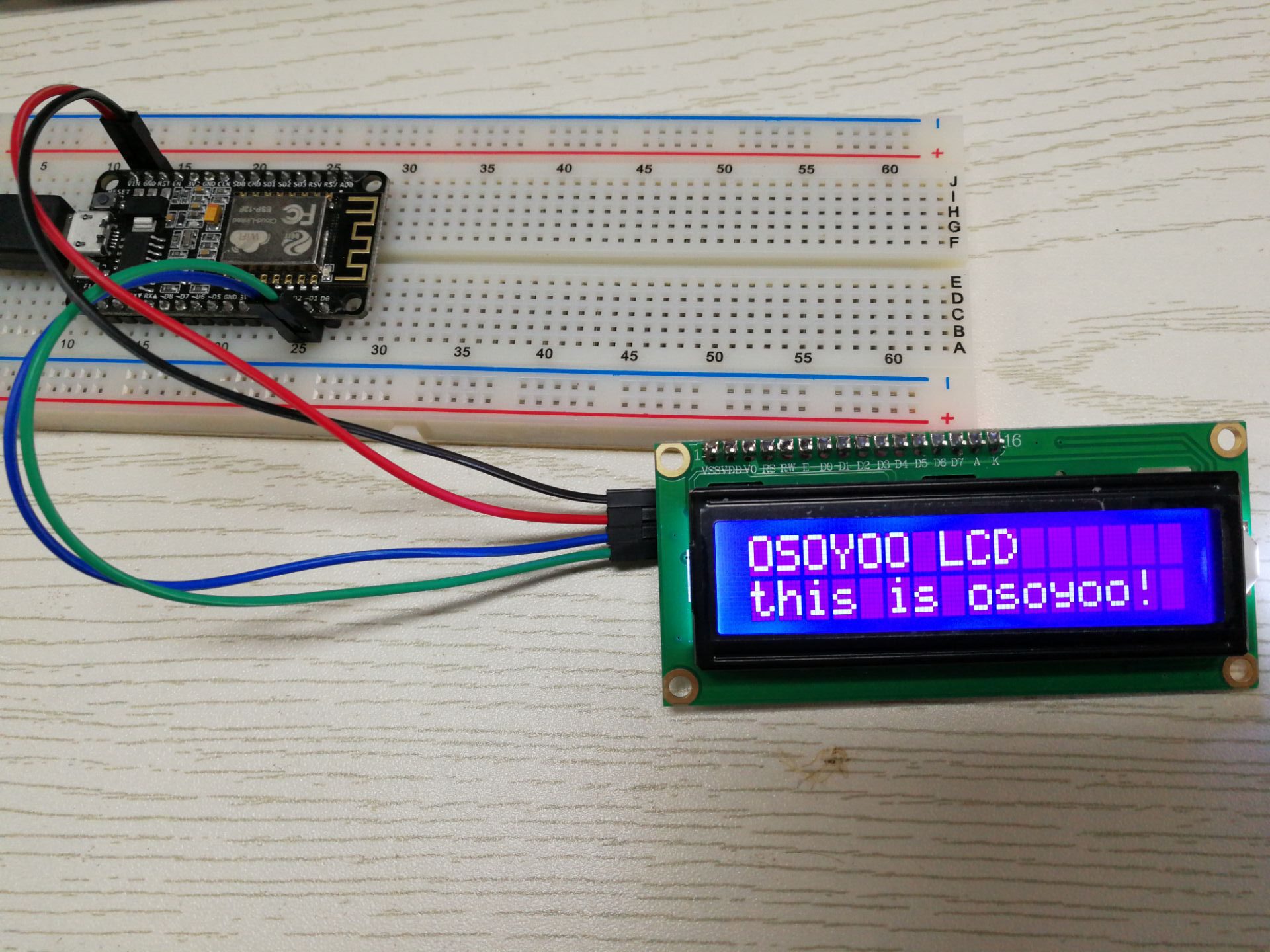
Getting Started with the Osoyoo NodeMCU Kit
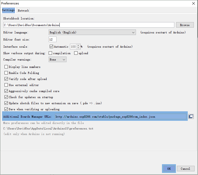
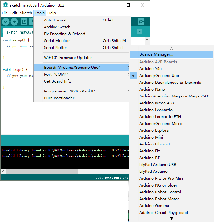
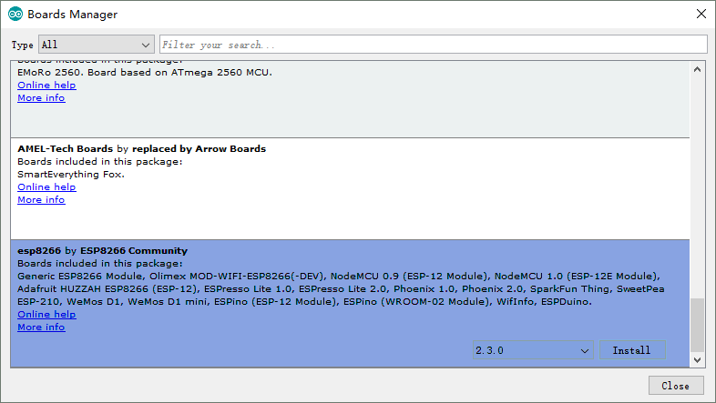
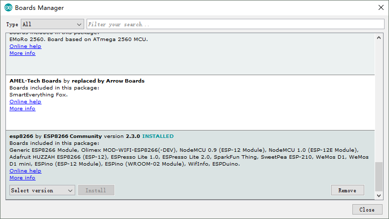
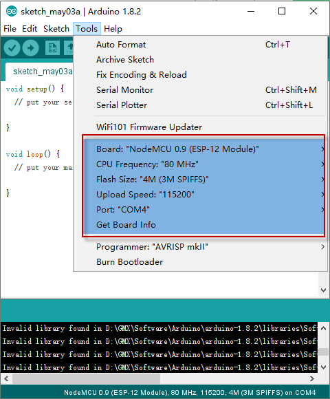
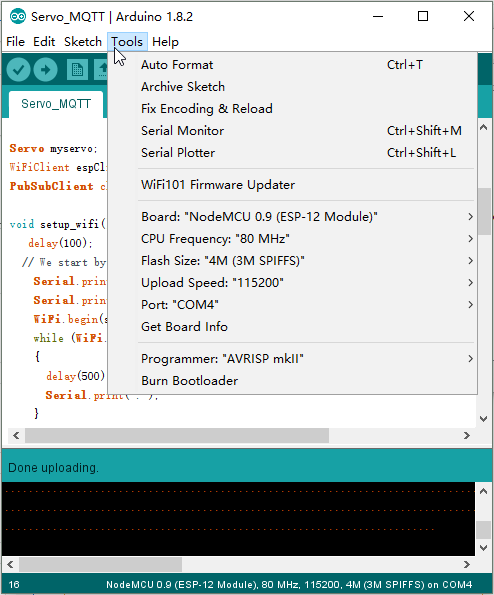
- Using Arduino IDE
- Using NodeMCU Lua
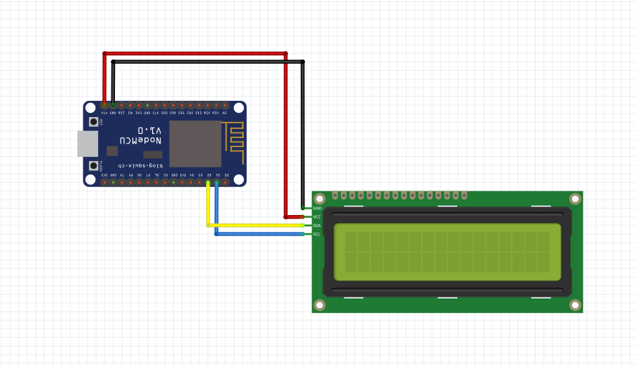
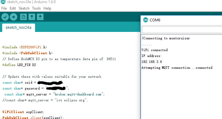
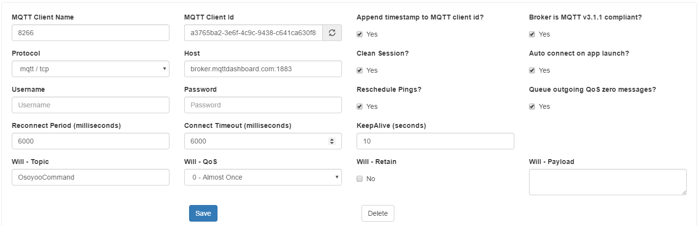
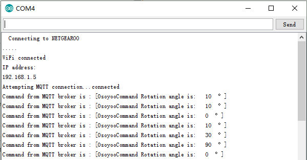
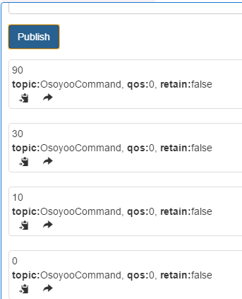
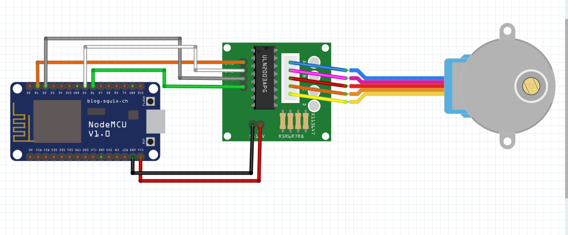
Tutorial and sample projects(Arduino IDE)
FAQ
You can list you question here or contact with support@vership.com for technology support.
When I connect stuff to some of the pins, the NodeMCU stops working. Whats up with that?
The ESP8266 uses some of the pins as 'boot mode' pins so on boot they must be set to certain values:
- CH_PD (EN) should be always pulled high (it will disable the entire module if low)
- RST should be always pulled high (it will disable the entire module if low)
- GPIO 0 sets whether the bootloader is active, it must be pulled HIGH during power up/reset for
- the user program to run. If its pulled LOW, it will activate the bootloader. The built-in red LED on
- #0 pulls it up
- GPIO 2 must be pulled high on power up/reset.
- GPIO 15 must be pulled low on power up/reset.
My NodeMCU board keeps crashing and resetting, whats up with that?
The most common reason for crashes is power failure. Make sure you're powering the NodeMCU
with a good ~5V power supply, and if you're using a USB-Serial cable, that its plugged into the
mainboard of your computer or through a powered hub!
I can't seem to find the Serial port on my computer for the NodeMCU?
Don't forget to install the Serial port driver(CP2104 driver / CH340 driver) or your computer, they are required!
I can't get Lua to respond to my commands
Make sure your terminal software is sending correct line endings! The default PuTTY settings may be
wrong when trying to talk to Lua on an ESP8266. Lua expects CRLF "\r\n" line endings, and apparently
PuTTY defaults to just LF "\n"!
Reference
ESP8266 Datasheet & Other Documents: http://www.esp8266.com/wiki/doku.php
NodeMCU-firmware: https://github.com/nodemcu/nodemcu-firmware
NodeMCU office website: http://www.nodemcu.com/
NodeMCU Documentation: https://nodemcu.readthedocs.io/en/master/
Windows flash tool: https://github.com/nodemcu/nodemcu-flasher
Linux flash tool: https://github.com/espressif/esptool
ESPlorer GUI: https://github.com/4refr0nt/ESPlorer