ESP8266 Webserver: Controlling a LED through WiFi
The objective of this post is to explain how to control a LED through WiFi, using the ESP8266.
Introduction
The objective of this post is to explain how to control a LED wirelessly through WiFi, with the ESP8266 acting as a web server.
Most of the code used here will be based on previous tutorials, so only a brief explanation will be done. In the related posts section bellow, I will leave links for all the relevant related posts.
If you are using a development board such as the NodeMCU, you can use the built in LED to test the code presented in this tutorial without the needed for additional hardware. If your development board doesn’t have a controllable LED, you can check this previous post on how to control a LED with the ESP8266.
The setup code
Most of the relevant code will be similar to the one of this previous post where we explained how to set a simple HTTP web server with the ESP8266.
So, we start by including the libraries needed to connect the ESP8266 to a WiFi network and to set the HTTP server.
#include <ESP8266WiFi.h>
#include <ESP8266WebServer.h>
#include <ESP8266WebServer.h>
Next, we declare a global object variable from the ESP8266WebServer class. This class will have the methods needed to set the HTTP server.
ESP8266WebServer server(80);
We passed 80 for the constructor, which indicates that the server will be listening on port 80.
We will also declare a global variable to specify the LED pin and another for its state (on or off).
int ledPin = 16;
bool ledState = LOW;
bool ledState = LOW;
There is no problem in initializing a Boolean variable with LOW because it will correspond to “0” [1]. Also, I’m using GPIO 16 because, on the NodeMCU (one of the most used ESP boards), it corresponds to the board’s LED pin.
We need to specify that the pin will be an output pin. We do this in the setup function.
pinMode(ledPin, OUTPUT);
Also in the setup function, we will specify the URLs where our server will be listening to incoming HTTP requests. We will define 3 URLs, one for each operation on the LED: turn on, turn off and toggle.
server.on(“/on”, turnOn); //Associate the handler function to the path
server.on(“/off”, turnOff); //Associate the handler function to the path
server.on(“/toggle”, toggle); //Associate the handler function to the path
server.on(“/off”, turnOff); //Associate the handler function to the path
server.on(“/toggle”, toggle); //Associate the handler function to the path
The first argument of the on method specifies the path where the server should listen, and the second argument specifies the name of the handling function that will be executed by the ESP8266 when a request to the corresponding path is received. We will specify those functions latter.
Bellow is the complete setup function. We start by connecting to the WiFi network, doing some prints to the serial port indicating if the connection was successful and we declare the paths of our HTTP server. We finalize the setup of our server by calling the begin method on the server object.
void setup() {
pinMode(ledPin, OUTPUT);
Serial.begin(115200);
WiFi.begin(“YourNetworkName”, “YourPassword”); //Connect to the WiFi network
WiFi.begin(“YourNetworkName”, “YourPassword”); //Connect to the WiFi network
while (WiFi.status() != WL_CONNECTED) { //Wait for connection
delay(500);
Serial.println(“Waiting to connect…”);
Serial.println(“Waiting to connect…”);
}
Serial.print(“IP address: “);
Serial.println(WiFi.localIP()); //Print the local IP
Serial.println(WiFi.localIP()); //Print the local IP
server.on(“/on”, turnOn); //Associate the handler function to the path
server.on(“/off”, turnOff); //Associate the handler function to the path
server.on(“/toggle”, toggle); //Associate the handler function to the path
server.on(“/off”, turnOff); //Associate the handler function to the path
server.on(“/toggle”, toggle); //Associate the handler function to the path
server.begin(); //Start the server
Serial.println(“Server listening”);
Serial.println(“Server listening”);
}
To handle the actual incoming of HTTP requests, we need to call the handleClient method on the server object, on the main loop function.
void loop() {
server.handleClient();
}
The handling functions
For the turnOn handler function, we will start by setting the ledState variable to HIGH, since we want to turn on the LED.
ledState = HIGH;
We then write the state of the LED with the digitalWrite function.
digitalWrite(ledPin, ledState);
In the last line of code of the handler function, we will just send the HTTP response, so the client knows the action was performed. If we remember the previous post, the first argument of the function is the HTTP response code, the second the type of content of the response, and the third the actual response.
server.send(200, “text/plain”, “LED on”);
You can check the full handling function bellow.
void turnOn(){
ledState = HIGH;
digitalWrite(ledPin, ledState);
server.send(200, “text/plain”, “LED on”);
digitalWrite(ledPin, ledState);
server.send(200, “text/plain”, “LED on”);
}
The handler for the turnOff URL is exactly the same, except for the fact that we will set the ledState variable to LOW.
void turnOff(){
ledState = LOW;
digitalWrite(ledPin, ledState);
server.send(200, “text/plain”, “LED off”);
digitalWrite(ledPin, ledState);
server.send(200, “text/plain”, “LED off”);
}
The toggling handling function is also similar, except that we apply the NOT operator to the ledState variable and assign it to itself.
void toggle(){
ledState = !ledState;
digitalWrite(ledPin, ledState);
server.send(200, “text/plain”, “LED toggled”);
digitalWrite(ledPin, ledState);
server.send(200, “text/plain”, “LED toggled”);
}
Important: When directly copying the code from the blog, a stray error may occur when trying to compile it on Arduino. In my case, this occurs because the editor assumes the wrong type of quotes. The easiest way to fix this, given the number of existing quotes, is to do a find and replace and put the correct quotes.
Testing the code
To test the code, we simply copy the IP that gets printed on the serial console and use it in a web browser in the format seen bellow.
For the on path, we should get the result shown in figure 1. Note that you will probably have a different IP, depending on which was assigned to the ESP on your network.
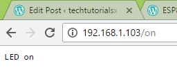
Figure 1 – LED on URL.
For the off path, we can see the expected output in figure 2.
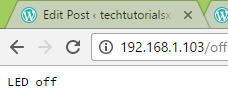
Figure 2 – LED off URL.
Finally, the result for the toggle path is shown in figure 3.
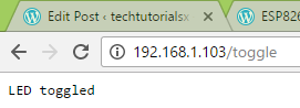
Figure 3 – LED toggle URL.
Important: If you are getting the opposite result on the LED in the on and off URLs, this may mean that the LED of your board is in an active low configuration (which is the case of the NodeMCU). In other words, the board is wired in a way that when the microcontroller output pin is in a LOW state, the LED turns on, and when it is in a HIGH state, the LED turns off.
Final notes
As we saw in this post, associating hardware functionality to a URL of the ESP8266 web server is very easy. Although we used 3 different endpoints, we could have only used one and allow the client to pass the state of the LED in the query parameters, for example.
When associating functionality to the handling functions, we need to consider that we should not leave the client waiting for a response for a long time, which may cause a timeout. If we need to perform an operation that takes some time, it’s always an option to consider doing it asynchronously.
Although this simple example may seem a little bit useless in the real world IoT, if we change the LED for a relay (the code is exactly the same, just a little bit of extra hardware), we can start controlling high power devices, such as lamps or heaters.


沒有留言:
張貼留言