源自於 https://www.technobyte.org/verilog-full-adder-behavioral-modeling/
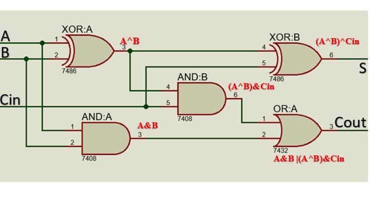
Logical diagram with the expression:
S = A ⊕ B ⊕ Cin
Cout = A.B + B.C + C.A
Cout = A & B | (A^B) & Cin
Truth Table for Full Adder:
| A | B | Cin | SUM (S) | CARRY (Cout) |
| 0 | 0 | 0 | 0 | 0 |
| 0 | 0 | 1 | 1 | 0 |
| 0 | 1 | 0 | 1 | 0 |
| 0 | 1 | 1 | 0 | 1 |
| 1 | 0 | 0 | 1 | 0 |
| 1 | 0 | 1 | 0 | 1 |
| 1 | 1 | 0 | 0 | 1 |
| 1 | 1 | 1 | 1 | 1 |
Methods of encoding a Full Adder using Behavioral Modeling
`timescale 1ns / 1ps module
full_adder( A, B, Cin, S, Cout);

 input wire A, B, Cin;
 output reg S, Cout;

 always @(A or B or Cin)
  begin
   S = A ^ B ^ Cin;
   Cout = A&B | (A^B) & Cin;
  end
endmodule
`timescale 1ns / 1ps module
full_adder(input wire A, B, Cin, output reg S, output reg Cout);

 always @(A or B or Cin)
  begin

   case (A | B | Cin)
     3'b000: begin S = 0; Cout = 0; end
     3'b001: begin S = 1; Cout = 0; end
     3'b010: begin S = 1; Cout = 0; end
     3'b011: begin S = 0; Cout = 1; end
     3'b100: begin S = 1; Cout = 0; end
     3'b101: begin S = 0; Cout = 1; end
     3'b110: begin S = 0; Cout = 1; end
     3'b111: begin S = 1; Cout = 1; end
   endcase

  end

endmodule
`timescale 1ns / 1ps
module full_adder( A, B, Cin, S, Cout);

input wire A, B, Cin;
output reg S, Cout;

always @(A or B or Cin)
begin
 if(A==0 && B==0 && Cin==0)
  begin
   S=0;
   Cout=0;
  end

 else if(A==0 && B==0 && Cin==1)
  begin
   S=1;
   Cout=0;
  end

 else if(A==0 && B==1 && Cin==0)
  begin
   S=1;
   Cout=0;
  end

 else if(A==0 && B==1 && Cin==1)
  begin
   S=0;
   Cout=1;
  end

 else if(A==1 && B==0 && Cin==0)
  begin
   S=1;
   Cout=0;
  end

 else if(A==1 && B==0 && Cin==1)
  begin
   S=0;
   Cout=1;
  end

 else if(A==1 && B==1 && Cin==0)
  begin
   S=0;
   Cout=1;
  end

 else if(A==1 && B==1 && Cin==1)
  begin
   S=1;
   Cout=1;
  end

end

endmodule
Testbench for full adder in Verilog
//timescale directive
`timescale 1ns / 1ps
module top;

  //declare testbench variables
  reg  A_input, B_input, C_input;
  wire Sum, C_output;

 //instantiate the design module and connect to the testbench variables
  full_adder instantiation(.A(A_input), .B(B_input), .Cin(C_input), .S(Sum), .Cout(C_output));

  initial
    begin
      $dumpfile("xyz.vcd");
      $dumpvars;

      //set stimulus to test the code
      A_input=0;
      B_input=0;
      C_input=0;
       #100 $finish;
    end

//provide the toggling input (just like truth table input)
//this acts as the clock input
always #40 A_input=~A_input;
always #20 B_input=~B_input;
always #10 C_input=~C_input;

//display output if there’s a change in the input event
  always @(A_input or B_input or C_input)
      $monitor("At TIME(in ns)=%t, A=%d B=%d C=%d Sum = %d Carry = %d", $time, A_input, B_input, C_input, Sum, C_output);

endmodule


沒有留言:
張貼留言