2020年4月1日 星期三

Shift Register using verilog

Shift Register using verilog


The picture shows the scheme of the shift register.


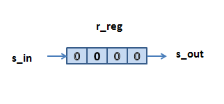
Here is the verilog implemmentation of shift register.


  1. // referencedesigner.com
  2. // Example of shift register
  3. module free_run_shift_reg
  4. #(parameter N=8)
  5. (
  6. input wire clk, reset,
  7. input wire s_in,
  8. output wire s_out
  9. );
  10. reg [N-1:0] r_reg;
  11. wire [N-1:0] r_next;
  12. always @(posedge clk, negedge reset)
  13. begin
  14. if (~reset)
  15. r_reg <= 0;
  16. else
  17. r_reg <= r_next;
  18. end
  19. assign r_next = {s_in, r_reg[N-1:1]};
  20. assign s_out = r_reg[0];
  21. endmodule


Explanation


Initially the reg value of undefined and hence we have placed 4'bxxxx in its value.

Because of the assign statement

assign s_out = r_reg[0];


the initial value of s_reg[0] is also 0.

When the reset pulse is applied the r_reg becomes 0000 at the next rising edge of clock. Note that the period of the negative level of the reset sould last at least to the next rising edge of the clock

At this stage, the value of s_out also becomes 0 ( right after the rising edge of the clock).

Now the s_in value is supplied sometimes before the next rising edge of the clock. Now because of the assign statement

assign r_next = {s_in, r_reg[N-1:1]};


the wire r_next is driven by the value of s_in and [3:1] bits of r_reg.

And so, after the application of the s_in, at the next rising edge of the clock, the statement


r_reg <= r_next;


in the always loop takes effect. which essentially results in updating the r_reg value with its value shifted to right and s_in coming in at its MSB.

The testbech for the Serial shift register

  1. `timescale 1ns / 1ps
  2. module stimulus;
  3. // Inputs
  4. reg clk ;
  5. reg reset;
  6. // Outputs
  7. reg s_in;
  8. wire s_out;
  9. // Instantiate the Unit Under Test (UUT)
  10. free_run_shift_reg #(2) s1 (
  11. .clk(clk),
  12. .reset(reset),
  13. .s_in(s_in),
  14. .s_out(s_out)
  15. );
  16. integer i, j;
  17. initial
  18. begin
  19. clk = 0;
  20. for(i =0; i<=40; i=i+1)
  21. begin
  22. #10 clk = ~clk;
  23. end
  24. end
  25.  initial
  26. begin
  27. $dumpfile("test.vcd");
  28. $dumpvars(0,stimulus);
  29. s_in = 0; reset =1;
  30. #2 s_in = 0 ; reset = 0;
  31. #2 reset =1;
  32. for(i =0; i<=10; i=i+1)
  33. begin
  34. #20 s_in = ~s_in;
  35. end
  36. #20 s_in =1;
  37. #20 s_in = 1;
  38. #20 s_in =0;
  39. #20 s_in =1;
  40. #20 s_in = 1;
  41. #20 s_in =0;
  42. #20 s_in =1;
  43. #20 s_in = 1;
  44. #20 s_in =0;
  45. end
  46. initial begin
  47. $monitor("clk=%d s_in=%d,s_out=%d",clk,s_in, s_out);
  48. end
  49. endmodule

沒有留言:

張貼留言

2024產專班 作業2 (純模擬)

2024產專班 作業2  (純模擬) 1) LED ON,OFF,TIMER,FLASH 模擬 (switch 控制) 2)RFID卡號模擬 (buttom  模擬RFID UID(不從ESP32) Node-Red 程式 [{"id":"d8886...