Verilog HDL: The First Example
Module, I/O Ports, Bus, and Assign
A Verilog module of a circuit encapsulates a description of its functionality as a structural or behavioral view of its input-output relationship. A structural view could be as simple as a netlist of gates or as complex as a high level architectural partition of the circuit into major functional blocks, such as an arithmetic and logic unit (ALU). A behavioral view could be a simple Boolean equation model, a register transfer level (RTL), or an algorithm. This section will look at the basics of a Verilog file.
A Simple Example
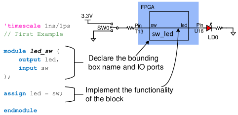
The general format for a Verilog circuit description is shown in the code below in Fig. 1. Required keywords have been shown in blue, comments in green, and key text strings the user must supply are shown in italics.
Module
In a schematic capture environment, a graphical symbol defines a given logic circuit by showing a “bounding box” as well as input and output connections. In Verilog, this same concept is used, only the bounding box must be explicitly typed into the text editor. The bounding box is defined with a module block and a corresponding port statement. The module block (as shown in the example) gives the circuit a name and defines all input and output ports, and so plays the same role as a symbol in a schematic environment. The module is closed by an “endmodule” statement, and all the statement between module declaration and “endmodule” describes the functionality of the module, i.e., the internal circuit connection of the module.
Input, Output, and Bus
Whenever you are writing a Verilog module, the first thing to do is to define the input and output signals. In the example in Fig. 1, there is one input signal “sw” coming from an on-board switch, and one output signal “led” connected to LED0. Note, however, that input and output can be a group of wires as well. We call these groupings a bus. To declare the input or output as a bus, we need to provide the CAD tools with the index of the most significant bit (MSB) of the bus and the index of the least significant bit (LSB) of the bus. For example, the following code defines an 8-bit wide bus “sw”, where the left-most bit (MSB) has the index 7 and the right-most bit (LSB) has the index 0.
input [7:0] sw
Indexing a bus in Verilog is similar to indexing an array in the C language. For example, if we want to index the second bit of sw bus declared above, we will use sw[1].
Assign Statement
The assign statement in the example above assigns the signal value on the net “sw” to the net “led”. In implementation, it creates a wire that connects the input port sw to the output port LED.
An assign statement can also be used to assign one signal of a bus to one signal of another bus. For example, if we declared sw as an 8-bit wide bus and LED as an 8-bit wide bus, and we want to use second switch to control fourth LED, the code will be:
module led_sw(
output [7:0] led,
input [7:0] sw
);
assign led[3] = sw[1];
...
endmodule
Constants
You can also assign a constant number to a signal or a bus to tie them to either logic '1' (VDD) or logic '0' (GND). The basic syntax for a constant number in Verilog is:
<Width in bits>'<base letter><number>
For example:
| Constant in Verilog | Explanation | Value in Binary |
|---|---|---|
| 12'h123 | 12 bits Hexadecimal 123 | 0001 0010 0011 |
| 20'd44 | 20 bits Decimal 44 | 0000 0000 0000 0010 1100 |
| 4'b1010 | 4 bits Binary 1010 | 1010 |
To tie a signal or a bus to constant, we can use assign statement as well. For example, if we are going to tie an 8-bit bus “seg” to ground, we will write:
module top (
...
output [7:0] seg,
...
);
assign seg = 8'd0;
...
endmodule
Important Ideas
- Module in Verilog HDL acts like the bounding box in circuit schematic.
- Bus is a group of signals (wires).
- Assign statement passes the value of a signal/bus to another signal/bus.
- Constant in Verilog HDL is presented in form of <Width in bits>'<base letter><number>


沒有留言:
張貼留言