Convert Binary numbers to BCD in Verilog
Drive a 7-Segment Display using a Double Dabbler on an FPGA
This module takes an input binary vector and converts it to Binary Coded Decimal (BCD). Binary coded decimal is used to represent a decimal number with four bits. This can be used to convert a binary number to a decimal number than can be displayed on a 7-Segment LED display. The algorithm used in the code below is known as a Double Dabble.
Binary coded decimal uses four bits per digit to represent a decimal number. For example the number 159 in decimal takes 12 bits to represent. This is useful for applications that interface to 7-Segment LEDs, among other things. The reason for this is that each 7-Segment display is treated individually (each gets 4 bits of the 12 bit number in the example above). The FPGA designer needs to know how to drive each digit, and uses BCD to do this. The table for BCD is below.
| BCD and Decimal Numbers | |
|---|---|
| BCD | Decimal |
| 0000 | 0 |
| 0001 | 1 |
| 0010 | 2 |
| 0011 | 3 |
| 0100 | 4 |
| 0101 | 5 |
| 0110 | 6 |
| 0111 | 7 |
| 1000 | 8 |
| 1001 | 9 |
| others | undefined |
Let's look at 159. The hundreds digit 1 is represented in binary by 0001. The tens digit 5 is represented in binary by 0101. The ones digit 9 is represented in binary by 1001. The entire number 159 in BCD is therefore: 000101011001. However 159 in binary is represented by 10011111. Again we need a way to convert this binary number 10011111 to its BCD equivalent 000101011001. To do this, we will use the Double Dabble algorithm.
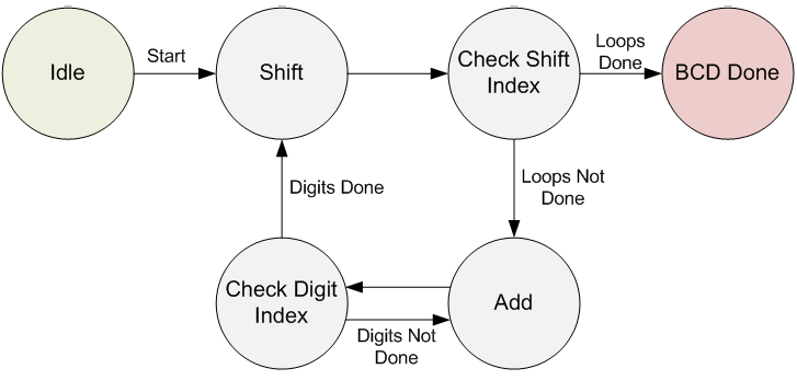
The Double Dabble Algorithm is described in detail on the linked Wikipedia page. But basically it takes the input binary number as a start. It shifts it one bit at a time into the BCD output vector. It then looks at each 4-bit BCD digit independently. If any of the digits are greater than 4, that digit is incremented by 3. This loop continues for each bit in the input binary vector. See the image below for a visual depiction of how the Finite State Machine is written.

Double Dabble Finite State Machine
Verilog Implementation
Binary_To_BCD.v:
1
2
3
4
5
6
7
8
9
10
11
12
13
14
15
16
17
18
19
20
21
22
23
24
25
26
27
28
29
30
31
32
33
34
35
36
37
38
39
40
41
42
43
44
45
46
47
48
49
50
51
52
53
54
55
56
57
58
59
60
61
62
63
64
65
66
67
68
69
70
71
72
73
74
75
76
77
78
79
80
81
82
83
84
85
86
87
88
89
90
91
92
93
94
95
96
97
98
99
100
101
102
103
104
105
106
107
108
109
110
111
112
113
114
115
116
117
118
119
120
121
122
123
124
125
126
127
128
129
130
131
132
133
134
135
136
137
138
139
| ///////////////////////////////////////////////////////////////////////////////// File Downloaded from http://www.nandland.com///////////////////////////////////////////////////////////////////////////////module Binary_to_BCD #(parameter INPUT_WIDTH, parameter DECIMAL_DIGITS) ( input i_Clock, input [INPUT_WIDTH-1:0] i_Binary, input i_Start, // output [DECIMAL_DIGITS*4-1:0] o_BCD, output o_DV ); parameter s_IDLE = 3'b000; parameter s_SHIFT = 3'b001; parameter s_CHECK_SHIFT_INDEX = 3'b010; parameter s_ADD = 3'b011; parameter s_CHECK_DIGIT_INDEX = 3'b100; parameter s_BCD_DONE = 3'b101; reg [2:0] r_SM_Main = s_IDLE; // The vector that contains the output BCD reg [DECIMAL_DIGITS*4-1:0] r_BCD = 0; // The vector that contains the input binary value being shifted. reg [INPUT_WIDTH-1:0] r_Binary = 0; // Keeps track of which Decimal Digit we are indexing reg [DECIMAL_DIGITS-1:0] r_Digit_Index = 0; // Keeps track of which loop iteration we are on. // Number of loops performed = INPUT_WIDTH reg [7:0] r_Loop_Count = 0; wire [3:0] w_BCD_Digit; reg r_DV = 1'b0; always @(posedge i_Clock) begin case (r_SM_Main) // Stay in this state until i_Start comes along s_IDLE : begin r_DV <= 1'b0; if (i_Start == 1'b1) begin r_Binary <= i_Binary; r_SM_Main <= s_SHIFT; r_BCD <= 0; end else r_SM_Main <= s_IDLE; end // Always shift the BCD Vector until we have shifted all bits through // Shift the most significant bit of r_Binary into r_BCD lowest bit. s_SHIFT : begin r_BCD <= r_BCD << 1; r_BCD[0] <= r_Binary[INPUT_WIDTH-1]; r_Binary <= r_Binary << 1; r_SM_Main <= s_CHECK_SHIFT_INDEX; end // Check if we are done with shifting in r_Binary vector s_CHECK_SHIFT_INDEX : begin if (r_Loop_Count == INPUT_WIDTH-1) begin r_Loop_Count <= 0; r_SM_Main <= s_BCD_DONE; end else begin r_Loop_Count <= r_Loop_Count + 1; r_SM_Main <= s_ADD; end end // Break down each BCD Digit individually. Check them one-by-one to // see if they are greater than 4. If they are, increment by 3. // Put the result back into r_BCD Vector. s_ADD : begin if (w_BCD_Digit > 4) begin r_BCD[(r_Digit_Index*4)+:4] <= w_BCD_Digit + 3; end r_SM_Main <= s_CHECK_DIGIT_INDEX; end // Check if we are done incrementing all of the BCD Digits s_CHECK_DIGIT_INDEX : begin if (r_Digit_Index == DECIMAL_DIGITS-1) begin r_Digit_Index <= 0; r_SM_Main <= s_SHIFT; end else begin r_Digit_Index <= r_Digit_Index + 1; r_SM_Main <= s_ADD; end end s_BCD_DONE : begin r_DV <= 1'b1; r_SM_Main <= s_IDLE; end default : r_SM_Main <= s_IDLE; endcase end // always @ (posedge i_Clock) assign w_BCD_Digit = r_BCD[r_Digit_Index*4 +: 4]; assign o_BCD = r_BCD; assign o_DV = r_DV; endmodule // Binary_to_BCD |

