Dataflow modeling
module and_gate(a,b,out);
input a,b;
output out;

assign out = a&b;
endmodule
Definition of Net

A net data type must be used when a signal is:
- driven by the output of some device.
- declared as an input or inout port.
- on the left-hand side of a continuous assignment.
We will look at its practical application below.
- Verilog has different net types, such as wire, trior, wand, trireg, etc.
- Nets need to be declared too.
- They are primarily declared using the keyword wire. S
// nets from above AND gate
module and_in_out(A,B,out);
input wire A,B;//declaring the nets for the input
output wire out;//declaring the nets for the output
endmodule
Take a look at the example below to understand how vector nets are declared.
module adder_in_out(a,b,out);
input wire[2:0] a,b;
output wire[3:0] out; //3 out wires
endmodule
Continuous Assignment
assign <net_expression> = [drive_strength] [delay] <expression of different signals or constant value>
For instance, we have used an assignment statement in the above code for AND:
assign out = a&b;
Let’s see another example:
assign sum = in1 + in2; // in1 + in2 is evaluated and assigned to sum
Continuous Assignment on Vectors
module adder(a,b,sum);
input [2:0] a,b;
output [3:0] sum;

assign sum = a + b;
$display("a = %b, b = %b, sum=%b", a,b,sum);
endmodule
//Simulation log
a = 100, b = 111, sum = 1011 // (a = 4, b = 7, sum = 011, carry = 1)
The same code for 3-bit adder is written using concatenation below:
module adder(a,b,sum);
input [2:0] a,b;
output [2:0] sum; //sum is a vector
output carry; // carry is a scalar

assign {carry,sum} = a + b; //assigning result to a concatenation of scalar and vector
$display("a = %b, b = %b, sum=%b, carry = %b", a,b,sum,carry);
endmodule
Simulation log
a = 100, b = 111, sum = 011, carry = 1 //
Regular continuous assignment
It follows the steps shown:
- Declare net
- Write continuous assignment on the net
wire out; // net 'out' is declared
assign out = a&b; //continuous assignment on declared net
Implicit continuous assignment
wire out = a & b; // net declaration and assignment together
Implicit Net Declaration
wire a,b;
out = a&b; // out not declared as wire but an implicit wire declaration is done by the simulator
Delays
Regular Assignment Delay
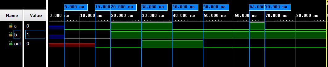
assign #10 out = a & b;
let’s see how the simulated waveform looks like for the following code:
module and_gate(a,b,out)
input a,b;
output out;

assign #10 out = a & b;
endmodule
Implicit Continuous Assignment Delay.
wire #10 out = a & b; //implicit Continuous Assignment Delay.
same as
wire out
assign #10 out = a & b;
Net Declaration Delay
wire #10 out;
assign out = a &b;
This code has the same effect as the following:
wire out
assign #10 out = a & b;


沒有留言:
張貼留言