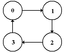
 The figure at left is the state diagram for a modulo-4
up-counter. It just counts 0, 1, 2, 3 and repeats, continually counting up (modulo 4). There is no input (other than the clock, which we almost never mention) and no output directly associated with the transitions. For this type of FSM, the output is associated with the states and not with the transitions.
Figure: State Diagram for a Modulo-4 Up-Counter
Many mathematical models of FSM focus on the state diagram. For most of our work, it is more convenient to work with the state table of the FSM, a tabular representation of the state diagram. Translation between the state diagram and state table is automatic. The state table presents the data in terms of present state Q(t) and next state Q(t+1) using the labeling that most naturally fits the problem. Here are the state tables for the two FSM above. Note that eh state table contains exactly the same information as the state diagram.
X = 0
|
X = 1
| |
A
|
A / 0
|
B / 0
|
B
|
A / 0
|
C / 0
|
C
|
D / 0
|
C / 0
|
D
|
A / 0
|
E / 0
|
E
|
A / 0
|
C / 1
|
Figure: State Table for 11011 Sequence Detector, Showing Output
0
|
1
|
1
|
2
|
2
|
3
|
3
|
0
|
Figure: State Table for a Modulo-Four Up-Counter


module mealy_mod_4(out, in, rst, clk);
output out;
input in;
input clk, rst;
reg [1:0]out=2'd0;
parameter s0=2'd0, s1=2'd1, s2=2'd2, s3=2'd3;
always @(posedge clk or negedge rst)
if(rst==0)begin
out=s0;
end
else begin
case (out)
s0:
if(in==0) begin
out=s1;
end
else begin
out=s3;
end
s1:
if(in==0) begin
out=s2;
end
else begin
out=s0;
end
s2:
if(in==0)begin
out=s3;
end
else begin
out=s1;
end
s3:
if(in==0) begin
out=s0;
end
else begin
out=s2;
end
default: out=s0;
endcase
end
endmodule
// 時間單位 100ns, 時間精確度100 ps
`timescale 100ns/100ps
module Test_bench;
reg in=0;
reg rst=1;
reg clk=1;
wire [1:0]out;
//module mealy_mod_4(out, in, rst, clk);
mealy_mod_4 DUT (.out(out) , .in(in) , .rst(rst), .clk(clk) );
initial begin
$monitor( in, rst, clk, out);
in=1'b1;
rst=1;
clk=1;
#60
in = 1'b1; rst = 1; //1
#60
in = 1'b1; rst = 1;
#60
in = 1'b1; rst = 1;
#60
in = 1'b1; rst = 1;
#60
in = 1'b1; rst = 1; //5
#60
in = 1'b0; rst = 1;
#60
in = 1'b0; rst = 1;
#60
in = 1'b0; rst = 1;
#60
in = 1'b0; rst = 1;
#60
in = 1'b0; rst = 1; //10
#60
in = 1'b0; rst = 1;
#60
in = 1'b0; rst = 1;
#60
in = 1'b1; rst = 1;
#60
in = 1'b1; rst = 0; //14
#60
in = 1'b0; rst = 0; //15
#60
in = 1'b0; rst = 0; //16
end
always #25 clk <= ~clk;
initial
begin
#1000; // 模擬終止時間 1500 ns
$stop;
end
endmodule


沒有留言:
張貼留言