源自於 https://www.geeksforgeeks.org/4-bit-binary-adder-subtractor/
源自於 http://www.barrywatson.se/dd/dd_adder_subtractor.html


module adder_subtractor_4bit(S, C, A, B, Op);
//module adder_subtractor_4bit(S, C, V, A, B, Op);
output [3:0] S; // The 4-bit sum/difference.
output C; // The 1-bit carry/borrow status.
//output V; // The 1-bit overflow status.
input [3:0] A; // The 4-bit augend/minuend.
input [3:0] B; // The 4-bit addend/subtrahend.
input Op; // The operation: 0 => Add, 1=>Subtract.
wire C0; // The carry out bit of fa0, the carry in bit of fa1.
wire C1; // The carry out bit of fa1, the carry in bit of fa2.
wire C2; // The carry out bit of fa2, the carry in bit of fa3.
wire C3; // The carry out bit of fa2, used to generate final carry/borrrow.
wire B0; // The xor'd result of B[0] and Op
wire B1; // The xor'd result of B[1] and Op
wire B2; // The xor'd result of B[2] and Op
wire B3; // The xor'd result of B[3] and Op
// Looking at the truth table for xor we see that
// B xor 0 = B, and
// B xor 1 = not(B).
// So, if Op==1 means we are subtracting, then
// adding A and B xor Op alog with setting the first
// carry bit to Op, will give us a result of
// A+B when Op==0, and A+not(B)+1 when Op==1.
// Note that not(B)+1 is the 2's complement of B, so
// this gives us subtraction.
xor(B0, B[0], Op);
xor(B1, B[1], Op);
xor(B2, B[2], Op);
xor(B3, B[3], Op);
xor(C, C3, Op); // Carry = C3 for addition, Carry = not(C3) for subtraction.
// xor(V, C3, C2); // If the two most significant carry output bits differ, then we have an overflow.
full_adder fa0(S[0], C0, A[0], B0, Op); // Least significant bit.
full_adder fa1(S[1], C1, A[1], B1, C0);
full_adder fa2(S[2], C2, A[2], B2, C1);
full_adder fa3(S[3], C3, A[3], B3, C2); // Most significant bit.
endmodule // ripple_carry_adder_subtractor
module full_adder(S, Cout, A, B, Cin);
output S,Cout;
input A,B,Cin;
wire w1,w2,w3,w4;
xor(w1, A, B);
xor(S, Cin, w1);
and(w2, A, B);
and(w3, A, Cin);
and(w4, B, Cin);
or(Cout, w2, w3, w4);
endmodule // full_adder
// 時間單位 100ns, 時間精確度100 ps
`timescale 100ns/100ps
module Test_bench;
// module adder_subtractor_4bit(S, C, V, A, B, Op);
reg [3:0] A; // The 4-bit augend/minuend.
reg [3:0] B; // The 4-bit addend/subtrahend.
reg Op; // The operation: 0 => Add, 1=>Subtract.
wire [3:0] S; // The 4-bit sum/difference.
wire C; // The 1-bit carry/borrow status.
// wire V; // The 1-bit overflow status.
//adder_subtractor_4bit UUT(S, C, V, A, B, Op);
adder_subtractor_4bit UUT(S, C, A, B, Op);
initial begin
$monitor ( A, B, Op ,S, C);
A=4'd0; B=4'd0; Op=1'd0;
#30; A = 4'b1000; B = 4'b1001;
#30; A = 4'b1010; B = 4'b1011;
#30; A = 4'b1110; B = 4'b0011;
#30; A = 4'b0110; B = 4'b0111;
#30; A = 4'b1110; B = 4'b1111;
Op=1'd1;
#30; A = 4'b1000; B = 4'b1001;
#30; A = 4'b1010; B = 4'b1011;
#30; A = 4'b1110; B = 4'b0011;
#30; A = 4'b0110; B = 4'b0111;
#30; A = 4'b1110; B = 4'b1111;
#30;
end
initial begin
#320 $stop;
end
endmodule // carry_lookahead_adder_tb
Example
As an example imagine we have four full adders. With these we can easily build a 4-bit ripple carry adder to calculate
A+B — we just link up the four half adders, the carry out of one becomes the carry in of another, and set the first carry in to 0. Now, if we want to calculate A+(-B) then we can use the same half adders if we invert the bits of B and set the first carry in to 1. This would add A and the 2's complement of B giving us our subtraction.
To build our 4-bit adder/subtractor circuit using a 4-bit ripple carry adder we need, along with the two input numbers to add/subtract (
A and B), an input telling us if we are to perform an addition or subtraction operation which we can call Op. Now, if we look at the definition of the XOR gate we see that B xor 0 = B and B xor 1 = not(B). We can use this in our negation of B if we set Op to 0 when adding and to 1 when subtracting. This in conjunction with setting the initial carry input of the ripple carry adder to Op gives us what we need. The following table shows how this works:Op | Operand 1 | Operand 2 | Initial carry | Result |
|---|---|---|---|---|
0 | A | B | 0 | A+B |
1 | A | not(B) | 1 | A-B |
The carry/borrow status bit output can also make use of the XOR gate. If
C is the carry output of the ripple carry adder, then we can set the carry/borrow output of the adder/subtractor to be C xor Op. The overflow status bit output is handled easily, as it is C3 xor C4 when C3 and C4 are the respective carry outputs of the third and fourth half adder respectively.4-bit binary Adder-Subtractor
In Digital Circuits, A Binary Adder-Subtractor is one which is capable of both addition and subtraction of binary numbers in one circuit itself. The operation being performed depends upon the binary value the control signal holds. It is one of the components of the ALU (Arithmetic Logic Unit).
This Circuit Requires prerequisite knowledge of Exor Gate, Binary Addition and Subtraction, Full Adder.
Lets consider two 4-bit binary numbers A and B as inputs to the Digital Circuit for the operation with digits
A0 A1 A2 A3 for A
B0 B1 B2 B3 for B
The circuit consists of 4 full adders since we are performing operation on 4-bit numbers. There is a control line K that holds a binary value of either 0 or 1 which determines that the operation being carried out is addition or subtraction.
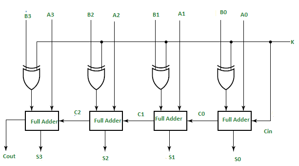
As shown in the figure, the first full adder has control line directly as its input(input carry C0), The input A0 (The least significant bit of A) is directly input in the full adder. The third input is the exor of B0 and K (S in fig But do not confuse it with Sum-S). The two outputs produced are Sum/Difference (S0) and Carry (C1).
If the value of K (Control line) is 1, th output of B0(exor)K=B0′(Complement B0). Thus the operation would be A+(B0′). Now 2’s complement subtraction for two numbers A and B is given by A+B’. This suggests that when K=1, the operation being performed on the four bit numbers is subtraction.
Similarly If the Value of K=0, B0 (exor) K=B0. The operation is A+B which is simple binary addition. This suggests that When K=0, the operation being performed on the four bit numbers is addition.
Then C0 is serially passed to the second full adder as one of it’s outputs.The sum/difference S0 is recorded as the least significant bit of the sum/difference. A1, A2, A3 are direct inputs to the second, third and fourth full adders.Then the third input is the B1, B2, B3 EXORed with K to the second, third and fourth full adder respectively. The carry C1, C2 are serially passed to the successive full adder as one of the inputs. C3 becomes the total carry to the sum/difference. S1, S2, S3 are recorded to form the result with S0.
For an n-bit binary adder-subtractor, we use n number of full adders.
Example:
Lets take two 3 bit numbers A=010 and B=011 and input them in the full adder with both values of control lines.
Lets take two 3 bit numbers A=010 and B=011 and input them in the full adder with both values of control lines.
For K=0:
B0(exor)K=B0 and C0=K=0

Thus from first full adder
= A0+B0
= 0+1
= 1,

S0=1
C1=0
Similarly,
S1=0 with C2=1
S2=1 and C2=0

Thus,
A = 010 =2
B = 011 = 3
Sum = 0101 = 5


For K=1
B0(exor)K=B0' and C0=k=1

Thus
S0=1 and C1=0
Similarly
S1=1 and C2=0
S3=1 and c3=1

Thus,
A = 010 = 2
B = 011 = 3
Sum(Difference) = 1111 = -1


沒有留言:
張貼留言