IMAGE AND VIDEO PROCESSING ON ALTERA DE2-115 USING NIOS II SOFT-CORE PROCESSOR
Term Project for ECE 576 Embedded System Design with FPGA
Fall 2014 Semester
By
Michael Barker, Master Student, MS in Electrical Engineering
Manaswi Yarradoddi, Master Student, MS in Electrical Engineering
Roshini Naidu, Master Student, MS in Embedded Systems
Advisor: Prof. Subramaniam Ganesan
Fall 2014 Semester
By
Michael Barker, Master Student, MS in Electrical Engineering
Manaswi Yarradoddi, Master Student, MS in Electrical Engineering
Roshini Naidu, Master Student, MS in Embedded Systems
Advisor: Prof. Subramaniam Ganesan
Introduction:
Click here to Download Presentation in pdf format
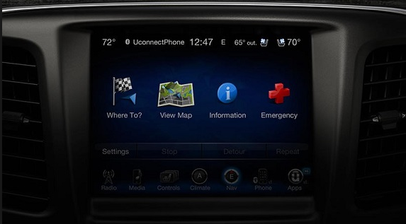
Image and video processing are used widely in automotive multimedia applications. Examples of such applications are navigation aids and driver information systems.
For the design project for this class we proposed to change the background of the image captured by the camera and displaying it on the Multi-Touch LCD screen. The goal of the project was to write a VHDL program that would connect a digital camera and a Multi- touch screen display to an FPGA board and capture live video from the digital camera. The captured image is then displayed on the touch screen display. Touching the image and bouncing and zooming it, moving it up and down, Right and left,diminishing the image and enlarging it. The hardware components necessary to develop such a project are a camera, LCD screen and Altera board.
The project utilizes the following hardware:
- Altera Video and Embedded Evaluation Kit
- Multi-touch (VEEK-MT) which includes:
- Altera DE2-115 FPGA development board.
- Digital camera.
- Multi-Touch LCD touch panel development kit.
- Altera Cyclone IV 4CE115 FPGA device
- Altera Serial Configuration device – EPCS64
- USB Blaster (on board) for programming; both JTAG and Active Serial (AS) programming modes are supported
- 2MB SRAM
- Two 64MB SDRAM
- 8MB Flash memory
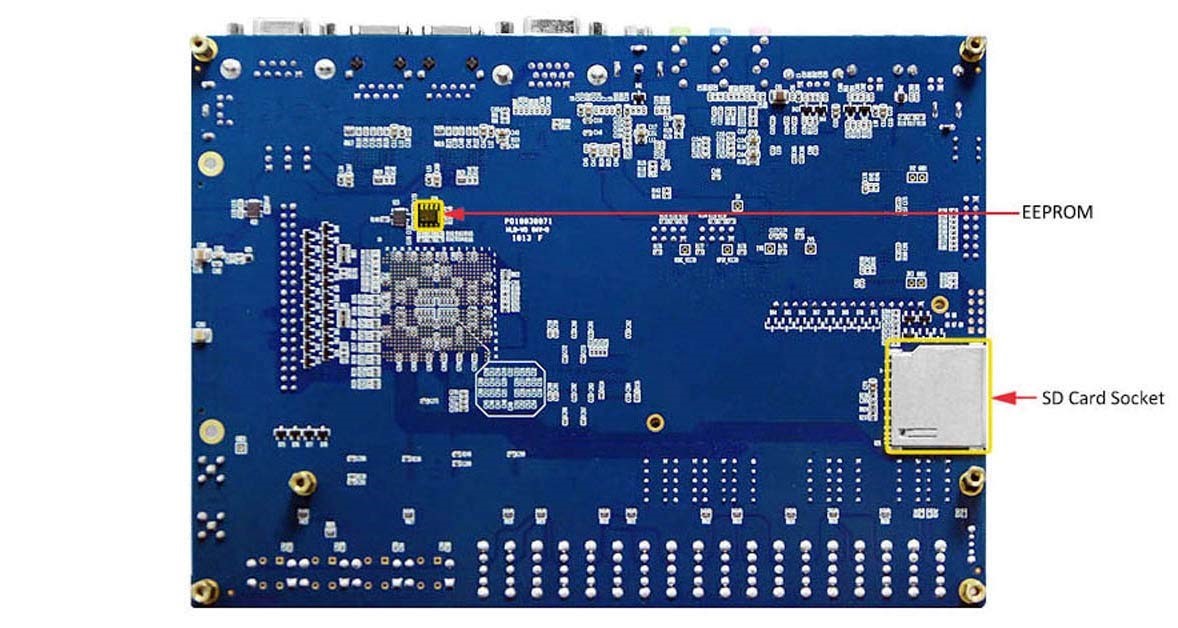
- SD Card socket
- 4 Push-buttons
- 18 Slide switches
- 18 Red user LEDs
- 9 Green user LEDs
- 50MHz oscillator for clock sources
- 24-bit CD-quality audio CODEC with line-in, line-out, and microphone-in jacks
- VGA DAC (8-bit high-speed triple DACs) with VGA-out connector
- TV Decoder (NTSC/PAL/SECAM) and TV-in connector
- 2 Gigabit Ethernet PHY with RJ45 connectors
- USB Host/Slave Controller with USB type A and type B connectors
- RS-232 transceiver and 9-pin connector
- PS/2 mouse/keyboard connector
- IR Receiver
- 2 SMA connectors for external clock input/output
- One 40-pin Expansion Header with diode protection
- One High Speed Mezzanine Card (HSMC) connector
- 16x2 LCD module
- Cyclone IV EP4CE115F29 device
- 114,480 LEs
- 432 M9K memory blocks
- 3,888 Kbits embedded memory
- 4 PLLs
- JTAG and AS mode configuration
- EPCS64 serial configuration device
- On-board USB Blaster circuitry
- 128MB (32Mx32bit) SDRAM
- 2MB (1Mx16) SRAM
- 8MB (4Mx16) Flash with 8-bit mode
- 32Kb EEPROM
- Provides SPI and 4-bit SD mode for SD Card access
- Two Ethernet 10/100/1000 Mbps ports
- High Speed Mezzanine Card (HSMC)
- Configurable I/O standards (voltage levels:3.3/2.5/1.8/1.5V)
- USB type A and B o Provide host and device controllers compliant with USB 2.0
- Support data transfer at full-speed and low-speed o PC driver available
- 40-pin expansion port
- Configurable I/O standards (voltage levels:3.3/2.5/1.8/1.5V)
- VGA-out connector
- VGA DAC (high speed triple DACs)
- DB9 serial connector for RS-232 port with flow control
- PS/2 mouse/keyboard
- Three 50MHz oscillator clock inputs
- SMA connectors (external clock input/output)
- 24-bit encoder/decoder (CODEC)
- Line-in, line-out, and microphone-in jacks
- 16x2 LCD module
- 18 slide switches and 4 push-buttons switches
- 18 red and 9 green LEDs
- Eight 7-segment displays
- Infrared remote-control receiver module
- TV decoder (NTSC/PAL/SECAM) and TV-in connector
- Desktop DC input
- Switching and step-down regulators LM3150MH
SYSTEM BLOCK DIAGRAM
The constant reduction both of cost and size of image sensors and the increasing complexity of FPGA circuits let us to design and implement an FPGA-based Digital Camera System. Also, due to the appearance of the LCD Touch Panels this system could be able to be controlled from such a panel. Furthermore, the flexibility of FPGAs gives us the possibility to integrate additional applications and image processing algorithms to the system without any cost in hardware. It’s worth mentioning that the hardware image processing algorithms could be faster than the corresponding algorithms in C/C++.
For the implementation of this system the development platform DE2 by Altera, the TRDB-D5M Camera and the TRDB-LTM LCD Touch Panel by Terasic have been chosen. Some of the DE2’s I/Os have been used for the interconnection of the Camera and the LCD Touch Panel as well as for the communication between the DE2 and a PC.
Hardware
Altera DE2-115 Board
The Altera® DE2-115 Development and Education board was designed by professors, for professors. It is an ideal vehicle for learning about digital logic, computer organization, and FPGAs. Featuring an Altera Cyclone® IV 4CE115 FPGA, the DE2-115 board is designed for university and college laboratory use. It is suitable for a wide range of exercises in courses on digital logic and computer organization, from simple tasks that illustrate fundamental concepts to advanced designs.
The DE2 series has consistently been at the forefront of educational development boards by distinguishing itself with an abundance of interfaces to accommodate various application needs. Extending its leadership and success, Terasic announces the latest DE2-115 that features the Cyclone IV E device. Responding to increased versatile low-cost spectrum needs driven by the demand for mobile video, voice, data access, and the hunger for high-quality images, the new DE2-115 offers an optimal balance of low cost, low power and a rich supply of logic, memory and DSP capabilities.The Cyclone EP4CE115 device equipped on the DE2-115 features 114,480 logic elements (LEs), the largest offered in the Cyclone IV E series, up to 3.9-Mbits of RAM, and 266 multipliers. In addition, it delivers an unprecedented combination of low cost and functionality, and lower power compared to previous generation Cyclone devices.The DE2-115 adopts similar features from the earlier DE2 series primarily the DE2-70, as well as additional interfaces to support mainstream protocols including Gigabit Ethernet (GbE). A High-Speed Mezzanine Card (HSMC) connector is provided to support additional functionality and connectivity via HSMC daughter cards and cables. For large-scale ASIC prototype development, a connection can be made with two or more FPGA-based boards by means of a HSMC cable through the HSMC connector.
The following pictures depicts the layout of the board and indicates the location of the connectors and key components:
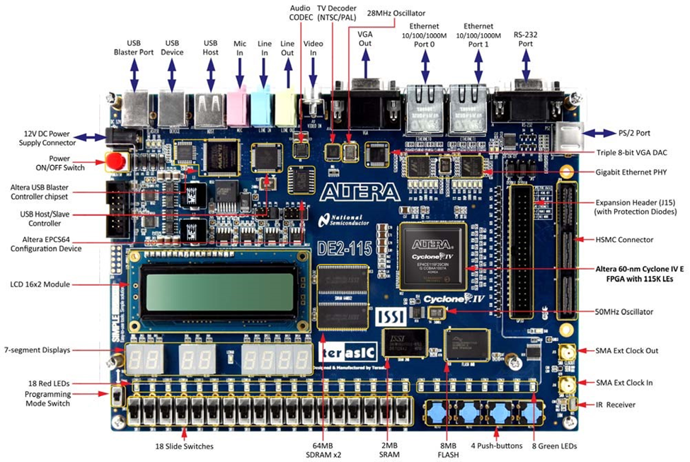
The DE2-115 board has many features that allow users to implement a wide range of designed circuits, from simple circuits to various multimedia projects.The following hardware is provided on the DE2-115 board:
In addition to these hardware features, the DE2-115 board has software support for standard I/O interfaces and a control panel facility for accessing various components. Also, the software is provided for supporting a number of demonstrations that illustrate the advanced capabilities of the DE2-115 board. In order to use the DE2-115 board, the user has to be familiar with the Quartus II software. The necessary knowledge can be acquired by reading the tutorials “Getting Started with Altera’s DE2-115 Board” (tut_initialDE2-115.pdf) and “Quartus II Introduction” (which exists in three versions based on the design entry method used, namely Verilog, VHDL or schematic entry). These tutorials are provided in the directory DE2_115_tutorials on the DE2-115 System CD that accompanies the DE2-115 kit and can also be found on Terasic’s DE2-115 web pages.
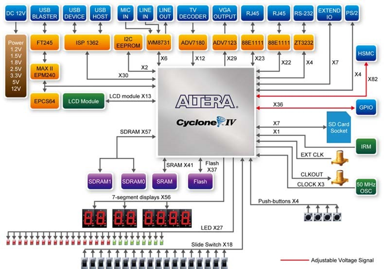
Block Diagram of the DE2-115 Board
This figure gives the block diagram of the DE2-115 board. To provide maximum flexibility for the user, all connections are made through the Cyclone IV E FPGA device. Thus, the user can configure the FPGA to implement any system design.
PGA device
FPGA configuration
Memory devices
SD Card socket
Connectors
Clock
Audio
Display
Switches and indicators
Other features
Power
LCD Module
The LCD module has built-in fonts and can be used to display text by sending appropriate commands to the display controller called HD44780. Detailed information for using the display is available in its datasheet, which can be found on the manufacturer’s website, and from the DE2_115_datasheets\LCD folder on the DE2-115 System CD.
A schematic diagram of the LCD module showing connections to the Cyclone IV E FPGA is given in figure below. The associated pin assignments appear in Table 1.
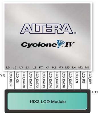
FIGURE 8 CONNECTIONS BETWEEN THE LCD MODULE AND CYCLONE IV E FPGA
Powering-up the DE2-115 Board
The DE2-115 board comes with a preloaded configuration bit stream to demonstrate some features of the board. This bit stream also allows users to see quickly if the board is working properly. To power-up the board perform the following steps:
1. Connect the provided USB cable from the host computer to the USB Blaster connector on the DE2-115 board. For communication between the host and the DE2-115 board, it is necessary to install the Altera USB Blaster driver software. If this driver is not already installed on the host computer, it can be installed as explained in the tutorial “Getting Started with Altera's DE2-115 Board ” (tut_initialDE2-115.pdf). This tutorial is available in the directory DE2_115_tutorials on the DE2-115 System CD.
2. Turn off the power by pressing the red ON/OFF switch before connecting the 12V adapter to the DE2-115 board.
3. Connect a VGA monitor to the VGA port on the DE2-115 board.
4. Connect your headset to the line-out audio port on the DE2-115 board.
5. Turn the RUN/PROG switch (SW19) on the left edge of the DE2-115 board to RUN position; the PROG position is used only for the AS Mode programming.
6. Recycle the power by turning the red power switch on the DE2-115 board OFF and ON again .
At this point you should observe the following:
• All user LEDs are flashing
• All 7-segment displays are cycling through the numbers 0 to F
• The LCD display shows “Welcome to the Altera DE2-115”
• The VGA monitor displays the image shown in Figure 2-4
• Set the slide switch SW17 to the DOWN position; you should hear a 1-kHz sound. Be careful of the very loud volume for avoiding any discomfort
• Set the slide switch SW17 to the UP position and connect the output of an audio player to the line-in connector on the DE2-115 board; on your speaker or headset you should hear the music played from the audio player (MP3, PC, iPod, or the like)
• You can also connect a microphone to the microphone-in connector on the DE2-115 board; your voice will be mixed with the music playing on the audio player
Configuring the Cyclone IV E FPGA
The procedure for downloading a circuit from a host computer to the DE2-115 board is described in the tutorial Quartus II Introduction. This tutorial is found in the DE2_115_tutorials folder on the DE2-115 System CD. The user is encouraged to read the tutorial first, and treat the information below as a short reference.
The DE2-115 board contains a serial configuration device that stores configuration data for the Cyclone IV E FPGA. This configuration data is automatically loaded from the configuration device into the FPGA every time while power is applied to the board. Using the Quartus II software, it is possible to reconfigure the FPGA at any time, and it is also possible to change the non-volatile data that is stored in the serial configuration device. Both types of programming methods are described below.
1. JTAG programming: In this method of programming, named after the IEEE standards Joint Test Action Group, the configuration bit stream is downloaded directly into the Cyclone IV E FPGA. The FPGA will retain this configuration as long as power is applied to the board; the configuration information will be lost when the power is turned off.
2. AS programming: In this method, called Active Serial programming, the configuration bit stream is downloaded into the Altera EPCS64 serial configuration device. It provides non-volatile storage of the bit stream, so that the information is retained even when the power supply to the DE2-115 board is turned off. When the board’s power is turned on, the configuration data in the EPCS64 device is automatically loaded into the Cyclone IV E FPGA.
Signal Name
|
FPGA Pin No.
|
Description
|
I/O
Standard
|
LCD_DATA[7]
|
PIN_M5
|
LCD Data[7]
|
3.3V
|
LCD_DATA[6]
|
PIN_M3
|
LCD Data[6]
|
3.3V
|
LCD_DATA[5]
|
PIN_K2
|
LCD Data[5]
|
3.3V
|
LCD_DATA[4]
|
PIN_K1
|
LCD Data[4]
|
3.3V
|
LCD_DATA[3]
|
PIN_K7
|
LCD Data[3]
|
3.3V
|
LCD_DATA[2]
|
PIN_L2
|
LCD Data[2]
|
3.3V
|
LCD_DATA[1]
|
PIN_L1
|
LCD Data[1]
|
3.3V
|
LCD_DATA[0]
|
PIN_L3
|
LCD Data[0]
|
3.3V
|
LCD_EN
|
PIN_L4
|
LCD Enable
|
3.3V
|
LCD_RW
|
PIN_M1
|
LCD Read/Write Select, 0 = Write, 1 = Read
|
3.3V
|
LCD_RS
|
PIN_M2
|
LCD Command/Data Select, 0 = Command, 1 = Data
|
3.3V
|
LCD_ON
|
PIN_L5
|
LCD Power ON/OFF
|
3.3V
|
LCD_BLON
|
PIN_L6
|
LCD Back Light ON/OFF
|
3.3V
|
TABLE 1 PIN ASSIGNMENT FOR LCD MODULE
VEEK-MT
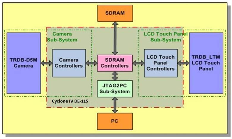
FIGURE 9 BLOCK DIAGRAM OF VEEK-MT KIT
The video and embedded evaluation kit with multi touch capability (VEEK-MT) is a product of Terasic. It is an Altera DE2-115 Development and Education Board with a 7 inch touch screen, ambient light sensor and CMOS digital image sensor. This kit is suitable for applications such as mobile video, data access, high quality images and voice applications. Its offers advantages in terms of lower power consumption, lower cost, and abundance of logic, memory and digital signal processing capabilities.
The Veek MT DE-115 FPGA board incorporates a capacitive LCD touch screen. The touchscreen made up of thin film transistor liquid crystal display. It has LED backlight. It has a parallel RGB interface.
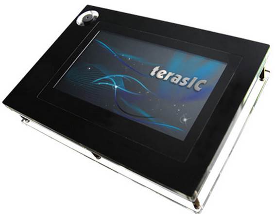
FIGURE 10 TOP VIEW OF TOUCH-SCREEN
The touch controller translates x,y coordinates of touch point into digital data. The diagonal length of the touch screen is 7 inches. Its resolution is 800x 3 RGB x 480. Its color arrangement is RGB-stripe. It is glare surface treatment. It has a dot pitch of 0.1926 in height and 0.1790 in width. It has an active area of 154.08 in height and 85.92 in width.
LCD Touch Panel Sub-System
The block diagram below shows the LCD Touch Panel Sub-System which displays the contents of the SDRAM on the LCD Touch Panel. It is also responsible for the touch detection on the panel. This sub-system consists of two parts, the LCD Touch Panel and the LCD controllers.
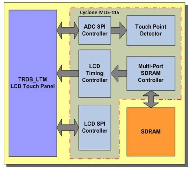
FIGURE 11 LCD TOUCH PANEL SUBSYSTEM
The LCD Touch Panel which has been chosen in this system is the TRDB_LTM by Terasic . Through the LCD Timing Controller the 24-bit display data stored in the SDRAM are displayed on the LCD Touch Panel. The values of the control registers of the LCD Touch Panel which are related to its functions are determined by the LCD SPI Controller.
Every time a touch is detected at any spot of the LCD Touch Panel, it reads and sends out the corresponding analog coordinates. An analog to digital converter (ADC) transforms the analog coordinates into the corresponding digital data which are sent to the FPGA through the second 40-pin expansion header of DE2-115.
It is worth noting that because of the limited number of I/Os of the expansion header, the LCD Touch Panel and the ADC share the same clock and chip enable signals. Consequently, during the design of the LCD SPI Controller there should be more attention given to the control of these signals in order to avoid the simultaneous use of the serial port interface by both the LCD Touch Panel and the ADC.
Finally, it should be noted that the resolution of the LCD Touch Panel is 800Hx480V. Because the image that captured from the Camera Sub-system has resolution 640Hx480V, two black bars are created in the sides of the LCD Touch Panel. In these bars the LCD Timing Controller draws the four buttons for the Camera control.
LCD Touch Panel Controllers
The following LCD Touch Panel Controllers which are responsible for the control of the LCD Touch Panel and the data transfer from DE2-115’s SDRAM, were designed in Verilog HDL [9, 10]:
• ADC SPI Controller
• Touch Point Detector Controller
• LCD Timing Controller
LCD SPI Controller
The ADC SPI controller receives the digital signals from the LCD Touch Panel’s ADC every time an area on the Panel is activated through touching. Then, it exports two 12-bit numbers which represent the x and y coordinates of the area that has been activated.
The Touch Point Detector Controller receives the coordinates of the activated areas and sends them to the 7Segment displays of the DE2 in order to be displayed. It also controls if the x and y coordinates reflect a point in one of the predefined active area.
Camera Interface
The Camera Sub-System which is presented in block diagram in the below figure, captures the image from the sensor, transforms it into RGB format and stores it in the SDRAM of DE2. The Camera Sub-System has two parts, the TRDB-D5M Camera and the Camera Controllers.
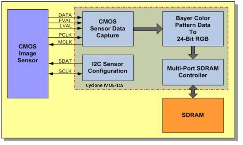
FIGURE 12 CAMERA INTERFACE BLOCK DIAGRAM
Image Sensor
The Veek MT DE-115 FPGA board has a 5 megapixel CMOS digital image sensor. The sensor has good low light performance. During reset, all rows expose at the same time. It has bulb exposure mode. It is capable of capturing frames on demand. It can do a vertical and horizontal mirror image. It uses a two wire serial interface. It is capable of improving image quality when resizing. It is possible to reduce image size without reducing field of view. There is programmable controls for gain, frame size, exposure and frame rate parameters. The sensor requires 3.3V power supply. The maximum signal to noise ratio is 38.1dB. The sensor has 70.1dB pixel dynamic range. It has a pixel size of 2.2um by 2.2um. It uses RGB Bayer pattern color filter array. It has a global reset release shutter type. Its maximum data rate is 96Mps at 96MHz master clock. The sensor has a 12 bit analog digital conversion resolution. During VGA mode, the sensor frame rate can be up to 70fps. During full resolution mode, the sensor frame rate can be up to 15fps.
Ambient Light Sensor
The Veek MT DE-115 FPGA board includes an ambient light sensor. It is next to the CMOS digital image sensor. It is used to estimate human-eye response. It allows accurate luminance measurement in various lighting conditions. It has a programmable interrupt function with adjustable lower and upper threshold. Analog gain and integration time can be programmed.
Terasic Video Image Processing (VIP core)
The Terasic Multi-Touch IP was obtained from the cd accompanying the Veek-MT module. The file is needed to use the multi-touch panel in the project. The frame reader function is used to read video from external memory and to output it as a stream. Switch function lets video stream switching in real time. Color space converter function changes image data between color spaces. Control synchronizer function alters the video stream in real time between two functions. 2D FIR filter function is a filter that smoothens images. Chroma re-sampler function alters the sample rate of chroma data. Clocked video input/output function changes BT-656 video format to Avalon ST video format and vice versa. Alpha blending mixer function mix and blends multiple image streams. Deinterlacer function uses motion adaptive deinterlacing algorithm to change interlaced video formats to progressive video format. Scaler II function performs custom scaling and real time
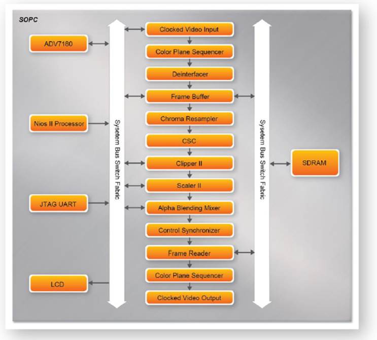
FIGURE 13 BLOCK DIAGRAM FOR VIP CORE
DE2-115 Control Panel
The DE2-115 board comes with a Control Panel facility that allows users to access various components on the board from a host computer. The host computer communicates with the board through a USB connection. The facility can be used to verify the functionality of components on the board or be used as a debug tool while developing RTL code. This section first presents some basic functions of the Control Panel, then describes its structure in block diagram form, and finally describes its capabilities.
Control Panel Setup
The Control Panel Software Utility is located in the directory
“DE2_115_tools/DE2_115_control_panel” in the DE2-115 System CD. It's free of installation, just copy the whole folder to your host computer and launch the control panel by executing the “DE2_115_ControlPanel.exe”. (Windows 7 64-bit Users: If an error message that shows a missing jtag_client.dll file (cannot find jtag_client.dll) while the Control Panel is commencing, users should re-launch the DE4_ControlPanel.exe from the following directory (/DE2_115_tools/DE2_115_control_panel/win7_64bits))
Specific control circuit should be downloaded to your FPGA board before the control panel can request it to perform required tasks. The program will call Quartus II tools to download the control circuit to the FPGA board through USB-Blaster [USB-0] connection.
To activate the Control Panel, perform the following steps:
1. Make sure Quartus II 10.0 or later version is installed successfully on your PC.
2. Set the RUN/PROG switch to the RUN position.
3. Connect the supplied USB cable to the USB Blaster port, connect the 12V power supply, and turn the power switch ON.
4. Start the executable DE2_115_ControlPanel.exe on the host computer. The Control Panel user interface shown in Figure 3-1 will appear.
5. The DE2_115_ControlPanel.sof bit stream is loaded automatically as soon as the DE2_115_control_panel.exe is launched.
6. In case the connection is disconnected, click on CONNECT where the .sof will be re-loaded onto the board.
7. Note, the Control Panel will occupy the USB port until you close that port; you cannot use Quartus II to download a configuration file into the FPGA until the USB port is closed.
8. The Control Panel is now ready for use; experience it by setting the ON/OFF status for some LEDs and observing the result on the DE2-115 board.
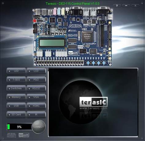
FIGURE 14 THE DE2-115 CONTROL PANEL
The concept of the DE2-115 Control Panel is illustrated in the above figure. The “Control Circuit” that performs the control functions is implemented in the FPGA board. It communicates with the Control Panel window, which is active on the host computer, via the USB Blaster link. The graphical interface is used to issue commands to the control circuit. It handles all requests and performs data transfers between the computer and the DE2-115 board.
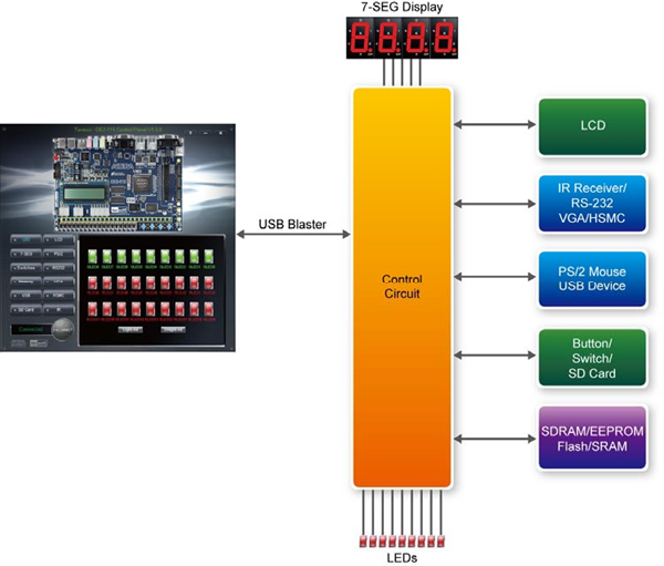
FIGURE 15 THE DE2-115 CONTROL PANEL CONCEPT
The DE2-115 Control Panel can be used to light up LEDs, change the values displayed on 7-segment and LCD displays, monitor buttons/switches status, read/write the SDRAM, SRAM, EEPROM and Flash Memory, monitor the status of an USB device, communicate with the PS/2 mouse, output VGA color pattern to VGA monitor, verify functionality of HSMC connector I/Os, communicate with PC via RS-232 interface and read SD Card specification information. The feature of reading/writing a word or an entire file from/to the Flash Memory allows the user to develop multimedia applications (Flash Audio Player, Flash Picture Viewer) without worrying about how to build a Memory Programmer.
Overall Structure of the DE2-115 Control Panel
The DE2-115 Control Panel is based on a Nios II SOPC system instantiated in the Cyclone IV E FPGA with software running on the on-chip memory. The software part is implemented in C code; the hardware part is implemented in Verilog HDL code with SOPC builder. The source code is not available on the DE2_115 System CD.
To run the Control Panel, users should make the configuration according to Section Figure below depicts the structure of the Control Panel. Each input/output device is controlled by the Nios II Processor instantiated in the FPGA chip. The communication with the PC is done via the USB Blaster link. The Nios II interprets the commands sent from the PC and performs the corresponding actions.
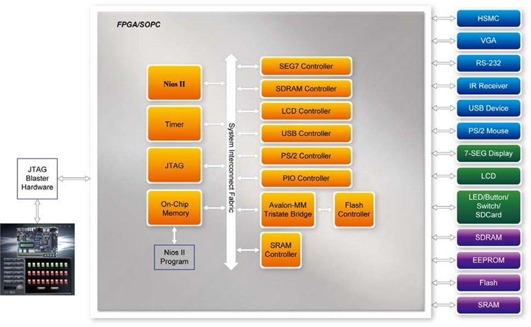
FIGURE 16 BLOCK DIAGRAM OF THE DE2-115 CONTROL PANEL
Controlling the LEDs, 7-segment Displays and LCD Display
A simple function of the Control Panel is to allow setting the values displayed on LEDs, 7-segment displays, and the LCD character display.
Choosing the LED tab leads to the window in the below figure. Here, you can directly turn the LEDs on or off individually or by clicking “Light All” or “Unlight All”.
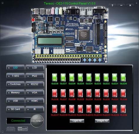
FIGURE 17 CONTROLLING LEDS
Choosing the 7-SEG tab leads to the window shown in the figure below. From the window, directly use the left-right arrows to control the 7-SEG patterns on the DE2-115 board which are updated immediately. Note that the dots of the 7-SEGs are not enabled on DE2-115 board.
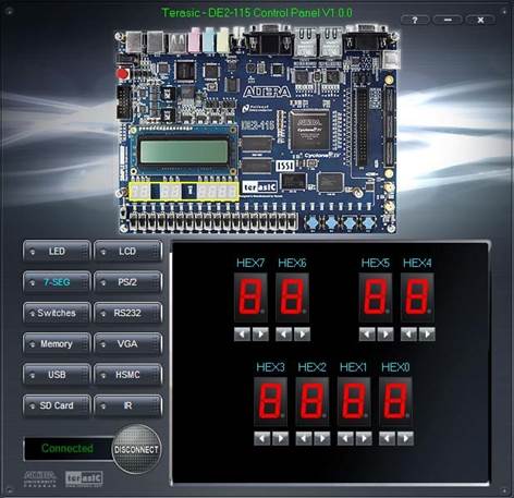
FIGURE 18 CONTROLLING 7-SEG DISPLAY
Choosing the LCD tab leads to the window in the figure below. Text can be written to the LCD display by typing it in the LCD box then pressing the Set button.
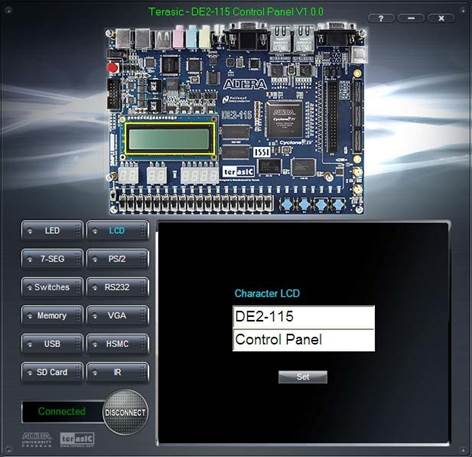
FIGURE 19 CONTROLLING THE LCD DISPLAY
The ability to set arbitrary values into simple display devices is not needed in typical design activities. However, it gives the user a simple mechanism for verifying that these devices are functioning correctly in case a malfunction is suspected. Thus, it can be used for troubleshooting purposes.
Switches and Push-buttons
Choosing the Switches tab leads to the window in the figure below. The function is designed to monitor the status of slide switches and push-buttons in real time and show the status in a graphical user interface. It can be used to verify the functionality of the slide switches and push-buttons.
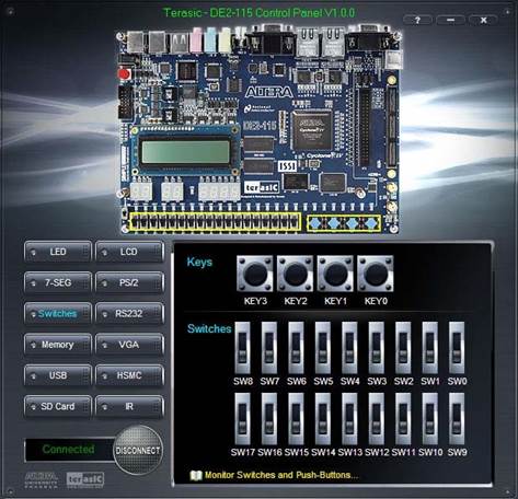
FIGURE 20 MONITORING SWITCHES AND BUTTONS
The ability to check the status of push-button and slide switch is not needed in typical design activities. However, it provides users a simple mechanism for verifying if the buttons and switches are functioning correctly. Thus, it can be used for troubleshooting purposes.
The DE2-115 board provides four push-button switches as shown in figure below. Each of these switches is debounced using a Schmitt Trigger circuit, as indicated in figure below. The four outputs called KEY0, KEY1, KEY2, and KEY3 of the Schmitt Trigger devices are connected directly to the Cyclone IV E FPGA. Each push-button switch provides a high logic level when it is not pressed, and provides a low logic level when depressed. Since the push-button switches are debounced, they are appropriate for using as clock or reset inputs in a circuit.
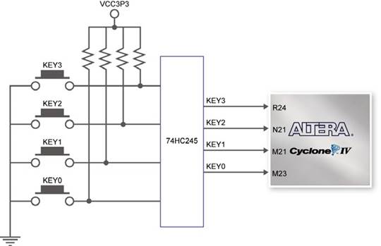
FIGURE 21 CONNECTIONS BETWEEN THE PUSH-BUTTON AND CYCLONE IV E FPGA
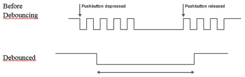
FIGURE 22 PUSH BUTTON DEBOUNCING
There are also 18 slide switches on the DE2-115 board. These switches are not debounced, and are assumed for use as level-sensitive data inputs to a circuit. Each switch is connected directly to a pin on the Cyclone IV E FPGA. When the switch is in the DOWN position (closest to the edge of the board), it provides a low logic level to the FPGA, and when the switch is in the UP position it provides a high logic level.
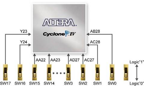
FIGURE 23 CONNECTIONS BETWEEN THE SLIDE SWITCHES AND CYCLONE IV E FPGA
LEDs
There are 27 user-controllable LEDs on the DE2-115 board. Eighteen red LEDs are situated above the 18 Slide switches, and eight green LEDs are found above the push-button switches (the 9th green LED is in the middle of the 7-segment displays). Each LED is driven directly by a pin on the Cyclone IV E FPGA; driving its associated pin to a high logic level turns the LED on, and driving the pin low turns it off. Figure Below shows the connections between LEDs and Cyclone IV E FPGA.
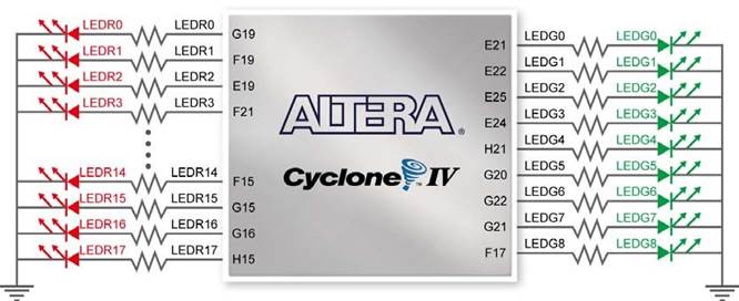
FIGURE 24 CONNECTIONS BETWEEN THE LEDS AND CYCLONE IV E FPGA
A list of the pin names on the Cyclone IV E FPGA that are connected to the slide switches is given in Table 4-1. Similarly, the pins used to connect to the push-button switches and LEDs are displayed in Table 2 and Table 3, respectively.
Signal Name
|
FPGA Pin No.
|
Description
|
I/O Standard
|
SW[0]
|
PIN_AB28
|
Slide Switch[0]
|
Depending on JP7
|
SW[1]
|
PIN_AC28
|
Slide Switch[1]
|
Depending on JP7
|
SW[2]
|
PIN_AC27
|
Slide Switch[2]
|
Depending on JP7
|
SW[3]
|
PIN_AD27
|
Slide Switch[3]
|
Depending on JP7
|
SW[4]
|
PIN_AB27
|
Slide Switch[4]
|
Depending on JP7
|
SW[5]
|
PIN_AC26
|
Slide Switch[5]
|
Depending on JP7
|
SW[6]
|
PIN_AD26
|
Slide Switch[6]
|
Depending on JP7
|
SW[7]
|
PIN_AB26
|
Slide Switch[7]
|
Depending on JP7
|
SW[8]
|
PIN_AC25
|
Slide Switch[8]
|
Depending on JP7
|
SW[9]
|
PIN_AB25
|
Slide Switch[9]
|
Depending on JP7
|
SW[10]
|
PIN_AC24
|
Slide Switch[10]
|
Depending on JP7
|
SW[11]
|
PIN_AB24
|
Slide Switch[11]
|
Depending on JP7
|
SW[12]
|
PIN_AB23
|
Slide Switch[12]
|
Depending on JP7
|
SW[13]
|
PIN_AA24
|
Slide Switch[13]
|
Depending on JP7
|
SW[14]
|
PIN_AA23
|
Slide Switch[14]
|
Depending on JP7
|
SW[15]
|
PIN_AA22
|
Slide Switch[15]
|
Depending on JP7
|
SW[16]
|
PIN_Y24
|
Slide Switch[16]
|
Depending on JP7
|
SW[17]
|
PIN_Y23
|
Slide Switch[17]
|
Depending on JP7
|
TABLE 2 PIN ASSIGNMENTS FOR SLIDE SWITCHES
Signal Name
|
FPGA Pin No.
|
Description
|
I/O Standard
|
KEY[0]
|
PIN_M23
|
Push-button[0]
|
Depending on JP7
|
KEY[1]
|
PIN_M21
|
Push-button[1]
|
Depending on JP7
|
KEY[2]
|
PIN_N21
|
Push-button[2]
|
Depending on JP7
|
KEY[3]
|
PIN_R24
|
Push-button[3]
|
Depending on JP7
|
TABLE 3 PIN ASSIGNMENTS FOR PUSH-BUTTONS
Signal Name
|
FPGA Pin No.
|
Description
|
I/O Standard
|
LEDR[0]
|
PIN_G19
|
LED Red[0]
|
2.5V
|
LEDR[1]
|
PIN_F19
|
LED Red[1]
|
2.5V
|
LEDR[2]
|
PIN_E19
|
LED Red[2]
|
2.5V
|
LEDR[3]
|
PIN_F21
|
LED Red[3]
|
2.5V
|
LEDR[4]
|
PIN_F18
|
LED Red[4]
|
2.5V
|
LEDR[5]
|
PIN_E18
|
LED Red[5]
|
2.5V
|
LEDR[6]
|
PIN_J19
|
LED Red[6]
|
2.5V
|
LEDR[7]
|
PIN_H19
|
LED Red[7]
|
2.5V
|
LEDR[8]
|
PIN_J17
|
LED Red[8]
|
2.5V
|
LEDR[9]
|
PIN_G17
|
LED Red[9]
|
2.5V
|
LEDR[10]
|
PIN_J15
|
LED Red[10]
|
2.5V
|
LEDR[11]
|
PIN_H16
|
LED Red[11]
|
2.5V
|
LEDR[12]
|
PIN_J16
|
LED Red[12]
|
2.5V
|
LEDR[13]
|
PIN_H17
|
LED Red[13]
|
2.5V
|
LEDR[14]
|
PIN_F15
|
LED Red[14]
|
2.5V
|
LEDR[15]
|
PIN_G15
|
LED Red[15]
|
2.5V
|
LEDR[16]
|
PIN_G16
|
LED Red[16]
|
2.5V
|
LEDR[17]
|
PIN_H15
|
LED Red[17]
|
2.5V
|
LEDG[0]
|
PIN_E21
|
LED Green[0]
|
2.5V
|
LEDG[1]
|
PIN_E22
|
LED Green[1]
|
2.5V
|
LEDG[2]
|
PIN_E25
|
LED Green[2]
|
2.5V
|
LEDG[3]
|
PIN_E24
|
LED Green[3]
|
2.5V
|
LEDG[4]
|
PIN_H21
|
LED Green[4]
|
2.5V
|
LEDG[5]
|
PIN_G20
|
LED Green[5]
|
2.5V
|
LEDG[6]
|
PIN_G22
|
LED Green[6]
|
2.5V
|
LEDG[7]
|
PIN_G21
|
LED Green[7]
|
2.5V
|
LEDG[8]
|
PIN_F17
|
LED Green[8]
|
2.5V
|
TABLE 4 PIN ASSIGNMENTS FOR LEDS
7-segment Displays
The DE2-115 Board has eight 7-segment displays. These displays are arranged into two pairs and a group of four, behaving the intent of displaying numbers of various sizes. As indicated in the schematic, the seven segments (common anode) are connected to pins on Cyclone IV E FPGA. Applying a low logic level to a segment will light it up and applying a high logic level turns it off.
Each segment in a display is identified by an index from 0 to 6, with the positions given in Figure 25. Table 5 shows the assignments of FPGA pins to the 7-segment displays.
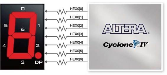
FIGURE 25 CONNECTIONS BETWEEN THE 7-SEGMENT DISPLAY HEX0 AND CYCLONE IV E FPGA
Signal Name
|
FPGA Pin No.
|
Description
|
I/O Standard
|
HEX0[0]
|
PIN_G18
|
Seven Segment Digit 0[0]
|
2.5V
|
HEX0[1]
|
PIN_F22
|
Seven Segment Digit 0[1]
|
2.5V
|
HEX0[2]
|
PIN_E17
|
Seven Segment Digit 0[2]
|
2.5V
|
HEX0[3]
|
PIN_L26
|
Seven Segment Digit 0[3]
|
Depending on JP7
|
HEX0[4]
|
PIN_L25
|
Seven Segment Digit 0[4]
|
Depending on JP7
|
HEX0[5]
|
PIN_J22
|
Seven Segment Digit 0[5]
|
Depending on JP7
|
HEX0[6]
|
PIN_H22
|
Seven Segment Digit 0[6]
|
Depending on JP7
|
HEX1[0]
|
PIN_M24
|
Seven Segment Digit 1[0]
|
Depending on JP7
|
HEX1[1]
|
PIN_Y22
|
Seven Segment Digit 1[1]
|
Depending on JP7
|
HEX1[2]
|
PIN_W21
|
Seven Segment Digit 1[2]
|
Depending on JP7
|
HEX1[3]
|
PIN_W22
|
Seven Segment Digit 1[3]
|
Depending on JP7
|
HEX1[4]
|
PIN_W25
|
Seven Segment Digit 1[4]
|
Depending on JP7
|
HEX1[5]
|
PIN_U23
|
Seven Segment Digit 1[5]
|
Depending on JP7
|
HEX1[6]
|
PIN_U24
|
Seven Segment Digit 1[6]
|
Depending on JP7
|
HEX2[0]
|
PIN_AA25
|
Seven Segment Digit 2[0]
|
Depending on JP7
|
HEX2[1]
|
PIN_AA26
|
Seven Segment Digit 2[1]
|
Depending on JP7
|
HEX2[2]
|
PIN_Y25
|
Seven Segment Digit 2[2]
|
Depending on JP7
|
HEX2[3]
|
PIN_W26
|
Seven Segment Digit 2[3]
|
Depending on JP7
|
HEX2[4]
|
PIN_Y26
|
Seven Segment Digit 2[4]
|
Depending on JP7
|
HEX2[5]
|
PIN_W27
|
Seven Segment Digit 2[5]
|
Depending on JP7
|
HEX2[6]
|
PIN_W28
|
Seven Segment Digit 2[6]
|
Depending on JP7
|
HEX3[0]
|
PIN_V21
|
Seven Segment Digit 3[0]
|
Depending on JP7
|
HEX3[1]
|
PIN_U21
|
Seven Segment Digit 3[1]
|
Depending on JP7
|
HEX3[2]
|
PIN_AB20
|
Seven Segment Digit 3[2]
|
Depending on JP6
|
HEX3[3]
|
PIN_AA21
|
Seven Segment Digit 3[3]
|
Depending on JP6
|
HEX3[4]
|
PIN_AD24
|
Seven Segment Digit 3[4]
|
Depending on JP6
|
HEX3[5]
|
PIN_AF23
|
Seven Segment Digit 3[5]
|
Depending on JP6
|
HEX3[6]
|
PIN_Y19
|
Seven Segment Digit 3[6]
|
Depending on JP6
|
HEX4[0]
|
PIN_AB19
|
Seven Segment Digit 4[0]
|
Depending on JP6
|
HEX4[1]
|
PIN_AA19
|
Seven Segment Digit 4[1]
|
Depending on JP6
|
HEX4[2]
|
PIN_AG21
|
Seven Segment Digit 4[2]
|
Depending on JP6
|
HEX4[3]
|
PIN_AH21
|
Seven Segment Digit 4[3]
|
Depending on JP6
|
HEX4[4]
|
PIN_AE19
|
Seven Segment Digit 4[4]
|
Depending on JP6
|
HEX4[5]
|
PIN_AF19
|
Seven Segment Digit 4[5]
|
Depending on JP6
|
HEX4[6]
|
PIN_AE18
|
Seven Segment Digit 4[6]
|
Depending on JP6
|
HEX5[0]
|
PIN_AD18
|
Seven Segment Digit 5[0]
|
Depending on JP6
|
HEX5[1]
|
PIN_AC18
|
Seven Segment Digit 5[1]
|
Depending on JP6
|
HEX5[2]
|
PIN_AB18
|
Seven Segment Digit 5[2]
|
Depending on JP6
|
HEX5[3]
|
PIN_AH19
|
Seven Segment Digit 5[3]
|
Depending on JP6
|
HEX5[4]
|
PIN_AG19
|
Seven Segment Digit 5[4]
|
Depending on JP6
|
HEX5[5]
|
PIN_AF18
|
Seven Segment Digit 5[5]
|
Depending on JP6
|
HEX5[6]
|
PIN_AH18
|
Seven Segment Digit 5[6]
|
Depending on JP6
|
HEX6[0]
|
PIN_AA17
|
Seven Segment Digit 6[0]
|
Depending on JP6
|
HEX6[1]
|
PIN_AB16
|
Seven Segment Digit 6[1]
|
Depending on JP6
|
HEX6[2]
|
PIN_AA16
|
Seven Segment Digit 6[2]
|
Depending on JP6
|
HEX6[3]
|
PIN_AB17
|
Seven Segment Digit 6[3]
|
Depending on JP6
|
HEX6[4]
|
PIN_AB15
|
Seven Segment Digit 6[4]
|
Depending on JP6
|
HEX6[5]
|
PIN_AA15
|
Seven Segment Digit 6[5]
|
Depending on JP6
|
HEX6[6]
|
PIN_AC17
|
Seven Segment Digit 6[6]
|
Depending on JP6
|
HEX7[0]
|
PIN_AD17
|
Seven Segment Digit 7[0]
|
Depending on JP6
|
HEX7[1]
|
PIN_AE17
|
Seven Segment Digit 7[1]
|
Depending on JP6
|
HEX7[2]
|
PIN_AG17
|
Seven Segment Digit 7[2]
|
Depending on JP6
|
HEX7[3]
|
PIN_AH17
|
Seven Segment Digit 7[3]
|
Depending on JP6
|
HEX7[4]
|
PIN_AF17
|
Seven Segment Digit 7[4]
|
Depending on JP6
|
HEX7[5]
|
PIN_AG18
|
Seven Segment Digit 7[5]
|
Depending on JP6
|
HEX7[6]
|
PIN_AA14
|
Seven Segment Digit 7[6]
|
3.3V
|
TABLE 5 PIN ASSIGNMENTS FOR 7-SEGMENT DISPLAYS
Memory Controller and Programmer
The Control Panel can be used to write/read data to/from the SDRAM, SRAM, EEPROM, and Flash chips on the DE2-115 board. As an example, we will describe how the SDRAM may be accessed; the same approach is used to access the SRAM, EEPROM, and Flash. Click on the Memory tab and select “SDRAM” to reach the window in the figure below.
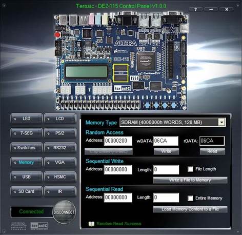
FIGURE 26 ACCESSING THE SDRAM
A 16-bit word can be written into the SDRAM by entering the address of the desired location, specifying the data to be written, and pressing the Write button. Contents of the location can be read by pressing the Read button. Above figure depicts the result of writing the hexadecimal value 06CA into offset address 200, followed by reading the same location.
The Sequential Write function of the Control Panel is used to write the contents of a file into the SDRAM as follows:
1. Specify the starting address in the Address box.
2. Specify the number of bytes to be written in the Length box. If the entire file is to be loaded, then a checkmark may be placed in the File Length box instead of giving the number of bytes.
3. To initiate the writing process, click on the Write a File to Memory button.
4. When the Control Panel responds with the standard Windows dialog box asking for the source file, specify the desired file in the usual manner.
The Control Panel also supports loading files with a .hex extension. Files with a .hex extension are ASCII text files that specify memory values using ASCII characters to represent hexadecimal values. For example, a file containing the line
0123456789ABCDEF
Defines eight 8-bit values: 01, 23, 45, 67, 89, AB, CD, EF. These values will be loaded consecutively into the memory.
The Sequential Read function is used to read the contents of the SDRAM and fill them into a file as follows:
1. Specify the starting address in the Address box.
2. Specify the number of bytes to be copied into the file in the Length box. If the entire contents of the SDRAM are to be copied (which involves all 128 Mbytes), then place a checkmark in the Entire Memory box.
3. Press Load Memory Content to a File button.
4. When the Control Panel responds with the standard Windows dialog box asking for the destination file, specify the desired file in the usual manner.
Users can use the similar way to access the SRAM, EEPROM and Flash. Please note that users need to erase the Flash before writing data to it.
USB Monitoring
The Control Panel provides users a USB monitoring tool which monitors the status of the USB devices connected to the USB port on the DE2-115 board. By plugging in a USB device to the USB host port of the board, the device type is displayed on the control window. Below Figure shows a USB mouse plugged into the host USB port.
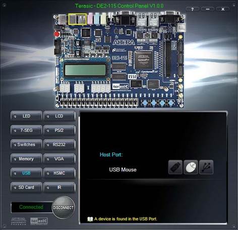
FIGURE 27 USB MOUSE MONITORING TOOL
PS/2 Device
The Control Panel provides users a PS/2 monitoring tool which monitors the real-time status of a PS/2 mouse connected to the DE2-115 board. The movement of the mouse and the status of the three buttons will be shown in the graphical and text interface. The mouse movement is translated as a position (x,y) with range from (0,0)~(1023,767). This function can be used to verify the functionality of the PS/2 connection.
Follow the steps below to exercise the PS/2 Mouse Monitoring tool:
1. Choosing the PS/2 tab leads to the window in the Figure Below.
2. Plug a PS/2 mouse to the PS/2 port on the DE2-115 board.
3. Press the Start button to start the PS/2 mouse monitoring process, and the button caption is changed from Start to Stop. In the monitoring process, the status of the PS/2 mouse is updated and shown in the Control Panel’s GUI window in real-time. Press Stop to terminate the monitoring process.
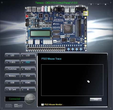
FIGURE 28 PS/2 MOUSE MONITORING TOOL
SD Card
The function is designed to read the identification and specification information of the SD Card. The 4-bit SD MODE is used to access the SD Card. This function can be used to verify the functionality of the SD Card Interface. Follow the steps below to exercise the SD Card:
1. Choosing the SD Card tab leads to the window in the figure below.
2. Insert an SD Card to the DE2-115 board, and then press the Read button to read the SD Card. The SD Card’s identification, specification, and file format information will be displayed in the control window.
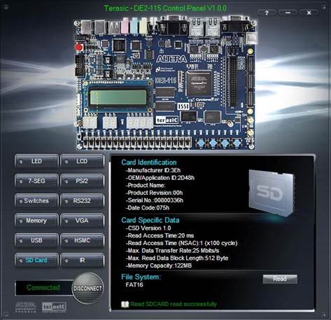
FIGURE 29 READING THE SD CARD IDENTIFICATION AND SPECIFICATION
VGA
DE2-115 Control Panel provides VGA pattern function that allows users to output color pattern to LCD/CRT monitor using the DE2-115 board. Follow the steps below to generate the VGA pattern function:
1. Choosing the VGA tab leads to the window in the figure below.
2. Plug a D-sub cable to VGA connector of the DE2-115 board and LCD/CRT monitor.
3. The LCD/CRT monitor will display the same color pattern on the control panel window.
4. Click the drop down menu shown in the figure below where you can output the selected color individually.
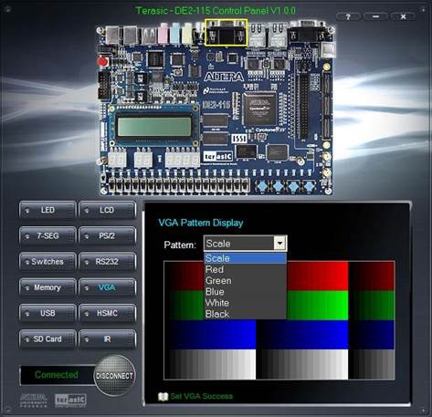
FIGURE 30 CONTROLLING VGA DISPLAY
HSMC
Select the HSMC tab to reach the window shown in the figure below. This function is designed to verify the functionality of the signals located on the HSMC connector. Before running the HSMC loopback verification test, follow the instruction noted under the Loopback Installation section and click on Verify. Please note to turn off the DE2-115 board before the HSMC loopback adapter is installed to prevent any damage to the board.
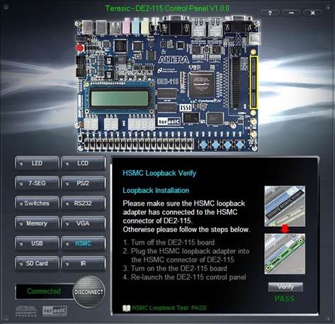
FIGURE 31 HSMC LOOPBACK VERIFICATION TEST PERFORMED UNDER CONTROL PANEL
RS-232 Communication
The Control Panel allows users to verify the operation of the RS-232 serial communication interface on the DE2-115. The setup is established by connecting a RS-232 9-pin male to female cable from the PC to the RS-232 port where the Control Panel communicates to the terminal emulator software on the PC, or vice versa. Alternatively, a RS-232 loopback cable can also be used if you do not wish to use the PC to verify the test. The Receive terminal window on the Control Panel monitors the serial communication status. Follow the steps below to initiate the RS-232 communication:
1. Choosing the RS-232 tab leads to the window in the figure below.
2. Plug in a RS-232 9-pin male to female cable from PC to RS-232 port or a RS-232 loopback cable directly to RS-232 port.
3. The RS-232 settings are provided below in case a connection from the PC is used:
• Baud Rate: 115200
• Parity Check Bit: None
• Data Bits: 8
• Stop Bits: 1
• Flow Control (CTS/RTS): ON
4. To begin the communication, enter specific letters followed by clicking Send. During the communication process, observe the status of the Receive terminal window to verify its operation.
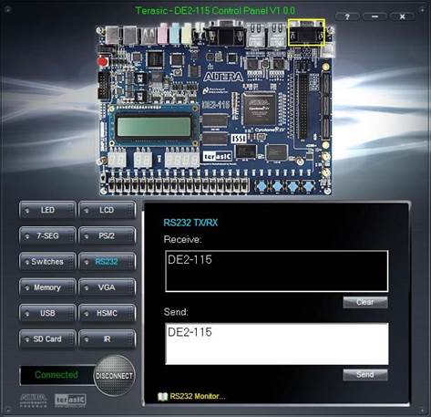
FIGURE 32 RS-232 SERIAL COMMUNICATION
Nios II Processor
Nios II is a soft-core processor targeted for Altera’s FPGA devices. As opposed to a fixed prefabricated processor, this soft-core processor is described by HDL codes and then mapped onto FPGA’s generic logic cells. Thus it can be configured and tuned by adding or removing features to meet performance or cost goals. This approach offers more flexibility.
There are three basic versions of Nios II in the SOPC Builder :
• Nios II/f: The fast core is designed for optimal performance. It has a 6-stage pipeline, instruction cache, data cache, and dynamic branch prediction.
• Nios II/s: The standard core is designed for small size while maintaining good performance. It has a 5-stage pipeline, instruction cache, and static branch prediction.
• Nios II/e: The economy core is designed for optimal size. It is not pipelined and contains no cache.
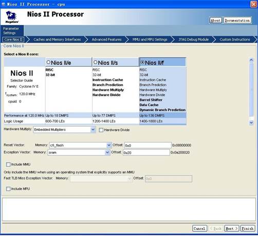
FIGURE 33 NIOS II PROCESSOR DIALOG
JTAG UART Core
The JTAG UART (Universal Asynchronous Receiver and Transmitter) core with Avalon interface provides a method to communicate serial character streams between a host PC and the board. On one side, the Nios II processor communicates with the core by reading and writing control and data registers. To increase the performance and regulate data transmission, a write FIFO buffer and a read FIFO buffer are also included in this core. On the other side, the core uses the JTAG circuitry built into Altera FPGA and provides host access via the JTAG pins on the FPGA. The host PC can connect to the FPGA via any Altera JTAG download cable, such as the USB-Blaster cable.
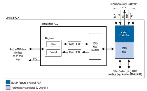
FIGURE 34 JTAG UART CORE BLOCK DIAGRAM
The software support for the JTAG UART core is provided by Altera as well. For the Nios II processor, device drivers are provided in the HAL (Hardware Abstraction Layer) system library, allowing software to access the core using the ANSI C Standard Library functions, such as getchar() and printf(). For the host PC, Altera provides JTAG terminal software NIOS EDS that manages the connection to the target, decodes the JTAG data stream, and displays characters on screen. The connection between a host PC and an Nios II system containing a JTAG UART core is shown below.
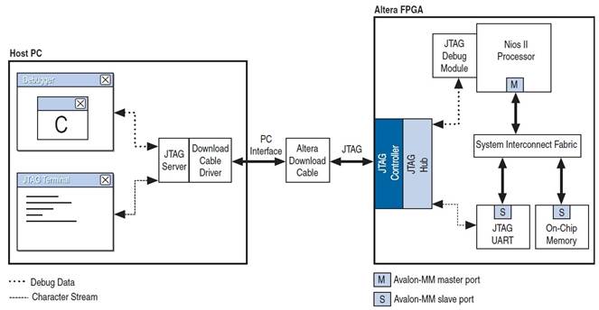
FIGURE 35 HOST-TARGET CONNECTION
The JTAG UART core in our Nios II system is used to debug the software program. For example, print out acceleration data or write image data into a file of the host PC. In the SOPC Builder, this core is configured in default settings. In our Nios II system, the size of Nios II processor is not a problem so Nios II/f is selected for optimal performance. The configuration dialog is displayed in Figure. In addition, we also need to specify the memories and locations of the reset vector and exception vector. A typical system usually adopts a nonvolatile memory module for the reset code. Thus the Flash memory is selected as the reset vector memory. Since our software program requires a relatively large amount of memory, SRAM is adopted as the exception vector memory. The other settings for our Nios II processor is default. Note that a level-1 JTAG debug module is used in the default setting.
Communication
JTAG Chain on DE2-115 Board
To use JTAG interface for configuring FPGA device, the JTAG chain on DE2-115 must form a close loop that allows Quartus II programmer to detect FPGA device. Figure illustrates the JTAG chain on DE2-115 board. Shorting pin1 and pin2 on JP3 can disable the JTAG signals on HSMC connector that will form a close JTAG loop chain on DE2-115 board. Thus, only the on board FPGA device (Cyclone IV E) will be detected by Quartus II programmer. If users want to include another FPGA device or interface containing FPGA device in the chain via HSMC connector, short pin2 and pin3 on JP3 to enable the JTAG signal ports on the HSMC connector.
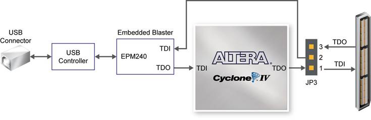
FIGURE 36 THE JTAG CHAIN ON DE2-115 BOARD
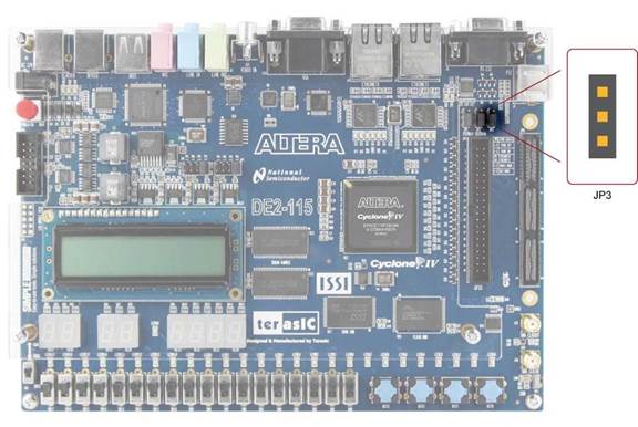
FIGURE 37 THE JTAG CHAIN CONFIGURATION HEADER
The sections below describe the steps used to perform both JTAG and AS programming. For both methods the DE2-115 board is connected to a host computer via a USB cable. Using this connection, the board will be identified by the host computer as an Altera USB Blaster device. The process for installing on the host computer the necessary software device driver that communicates with the USB Blaster is described in the tutorial “Getting Started with Altera’s DE2-115 Board” (tut_initialDE2-115.pdf). This tutorial is available on the DE2-115 System CD.
Configuring the FPGA in JTAG Module
Figure illustrates the JTAG configuration setup. To download a configuration bit stream into the Cyclone IV E FPGA, perform the following steps:
• Ensure that power is applied to the DE2-115 board
• Configure the JTAG programming circuit by setting the RUN/PROG slide switch (SW19) to the RUN position Connect the supplied USB cable to the USB Blaster port on the DE2-115 board
• The FPGA can now be programmed by using the Quartus II Programmer to select a configuration bit stream file with the .sof filename extension

FIGURE 38 THE JTAG CONFIGURATION SCHEME
FIGURE 39 THE RUN/PROG SWITCH (SW19) IS SET IN JTAG MODE
SD (SPI) Controller
SD (secure digital) card is a memory card widely used for massive storage. In this design, the SD card is utilized to store the raw image data and acceleration data. A block diagram of the SD card is shown in figure. It consists of a 9-pin interface, a card controller, a memory interface and a memory core. The 9-pin interface allows the exchange between a connected system and the card controller. The controller can read/write data from/to the memory core using the memory core interface. In addition, several internal registers are provided to store the state of the card.
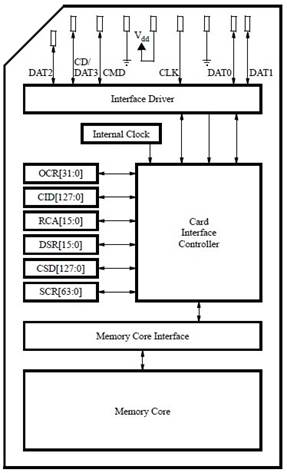
FIGURE 40 BLOCK DIAGRAM OF SD CARD
To interface with an SD card, the VEEK-MT features an SD card socket, on which pins labeled as CLK, CMD, DAT0, and CD/DAT3 are connected to the FPGA. The data exchange between the FPGA and the SD card can adopt one of the two modes: SD mode or SPI (Serial Peripheral Interface) mode. The SD mode is a proprietary format and uses four lines for data transfer. The SPI is an open standard for serial interfaces and is widely used in embedded applications. We selects SPI mode for SD card communication. Therefore the SD Controller in this Nios II system mainly implements the SPI protocol.
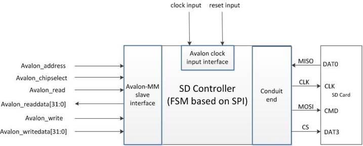
FIGURE 41 INPUT AND OUTPUT PORTS OF SD CONTROLLER
The SPI comprises four wires, clock (CLK), Master-Out Slave-In (MOSI), Master In Slave-Out (MISO) and chip select (CS). The clock signal CLK is generated by the master to synchronize the exchange of data. The MOSI line is used by the master to send commands and data to the slave, while the MISO line is used by the slave to respond to commands and send data back to the master. The fourth line CS enables or disables the slave device [14]. As shown in Figure 3.31, these four lines are connected to the pins CLK, CMD, DAT0 and DAT3 of SD card respectively. For illustrating the data transfer in SPI, it is assumed that there are two 8-bit shift registers, one in the master (FPGA chip or SD Controller) and one in the slave (SD card), shown by Figure . At the beginning of the operation, both the master and slave load data into the registers. Then at each CLK cycle, data in both registers is shifted to the left by one bit. After eight CLK cycles, eight data bits are shifted and the master and slave have exchanged register values. This operation can be interpreted that the master writes data to and reads data from the slave simultaneously, which is known as full-duplex operation. Note that for the SPI operation in SD card, the data are read at the rising edge and changed at the falling edge of the CLK signal.
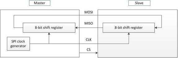
FIGURE 42 DATA TRANSFER IN SPI
I2C communication
An Inter-IC bus is often used to communicate across circuit-board distances. Here's a primer on the protocol. At the low end of the spectrum of communication options for "inside the box" communication is I2C ("eye-squared-see"). The name I2C is shorthand for a standard Inter-IC (integrated circuit) bus. I2C provides good support for communication with various slow, on-board peripheral devices that are accessed intermittently, while being extremely modest in its hardware resource needs. It is a simple, low-bandwidth, short-distance protocol. Most available I2C devices operate at speeds up to 400Kbps, with some venturing up into the low megahertz range. I2C is easy to use to link multiple devices together since it has a built-in addressing scheme.
Development Flow and Tools
The embedded SOPC system design consists of hardware development and software development, which are implemented by Quartus II Design Software and Nios II Embedded Design Suite respectively. Note that for VEEK-MT FPGA device (Cyclone IV E), 13.1 or later versions are necessary. We select version 13.1 as our development platforms. The basic development flow (mainly for our design) is shown in Figure 43.
QUARTUS II
The Altera Quartus II design software provides a complete, multiplatform design environment that easily adapts to your specific design needs. It is a comprehensive environment for system-on-a-programmable-chip (SOPC) design. The Quartus II software includes solutions for all phases of FPGA and CPLD design.
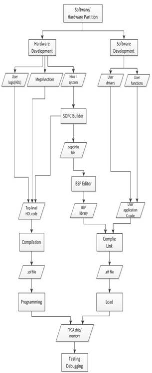
FIGURE 43 QUARTUS II DESIGN FLOW
SOPC Builder
SOPC Builder (System on a Programmable Chip Builder) is software made by Altera that automates connecting soft-hardware components to create a complete computer system that runs on any of its various FPGA chips. SOPC Builder incorporates a library of pre-made components (including the flagship Nios II soft processor, memory controllers, interfaces, and peripherals) and an interface for incorporating custom ones. Interconnections are made though the Avalon bus. Bus arbitration, bus width matching, and even clock domain crossing are all handled automatically when SOPC Builder generates the system. A GUI is the only thing used to configure the soft-hardware components (which often have many options) and to specify the bus topology. The resulting "virtual" system can then be connected to the outside world via the FPGA's programmable pins or connected internally to other soft compoments. The FPGA's pins are routed to connectors, such as for PCI or DDR, or -- as is often the case in embedded systems -- to other chips mounted on the same PCB.
Hardware Development Flow
The Altera Quartus II Design Software provides a complete, multi-platform design environment that easily adapts to specific hardware development. It includes solutions for all phases of FPGA and CPLD design through the easy-to-use graphical user interface. The left branch in Figure represents the Quartus II-based hardware design flow. A detailed description is given below:
Design Entry
We use Hardware Description Language (Verilog HDL), Mega Wizard Plug-In Manager and SOPC Builder to build system-level design. Mega functions are parameterizable functional blocks. The Mega Wizard Plug-In Manager allows one to create custom mega functions which can be instantiated in design files. The SOPC Builder can help implement customized Nios II system. In this software package, one can configure the Nios II soft processor, select the desired standard I/O cores, and incorporate the user designed I/O peripherals. Then the SOPC Builder generates the HDL code for the customized Nios II system and also generates the .sopcinfo file that contains system configuration information. This code is combined with other HDL code to form the top-level HDL description of the complete hardware. In addition, initial design constraints should be specified through Assignment editor and Settings dialog box.
Compilation
The compilation process consists of analysis and synthesis, fitting, timing analysis and assembling. This process realizes functions such as checking the syntax of HDL code, transforming HDL constructs to gate-level components, deriving the layout inside FPGA chip, performing timing analysis and finally producing programming files (.sof for JTAG programming, .pof for AS programming).
Programming and Debugging:
In this step, the configuration file is downloaded into the target device. The Signal Tap II Logic Analyzer can be used for debugging. This logic analyzer captures real-time signal behavior and supervises the interactions between hardware and software in the system design. The Quartus II software allows one to select signals to capture, when signal capture starts, and how many data samples to capture
Software Development Flow
The right branch in Figure represents the software design flow. The Altera Nios II Embedded Design Suite (EDS) is used for software development. It can be accessed by the SBT (Software Build Tools) command-line interface, by the SBT GUI, or by the IDE GUI. The SBT GUI is selected to develop the software in this design. The SBT GUI is based on the Eclipse open development environment and supports creating, modifying, building, running and debugging C programs targeted for a Nios II system. A Nios II software project contains two major parts: user applications and BSP (Board Support Package). The former is the user’s programs which include user I/O drivers and user high-level functions, and the latter is the support codes for a specific Nios II configuration. Note that the BSP is based on the information from the .sopcinfo file generated by SOPC Builder. The code from the two parts are compiled and linked into a single software image (.elf) and loaded into.
Software
Software Description (VIP_Camera)
Introduction
The VIP_Camera program includes components across all the different software utilities available in Quartus. All of the Verilog and Qsys components are written using Quartus 13.1. The NIOS II soft core processor is used and runs standard C++ code. The bulk of the work in the program is performed by the C++ code, with the hardware connections between the FPGA, DE2-115 and touch screen/video camera set up in Qsys and Verilog. The following diagram shows the overall layout and flow of the software.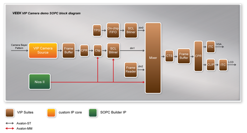
FIGURE 44 SOFTWARE FLOWCHART
Verilog
The Verilog portion of the program is primarily generated from the Qsys configuration but there’s a portion of it that is created for the specific integration with the DE2-115 board’s components. The code is contained in 9 different Verilog files split up into various components with one main file, VIP_Camera.v. This establishes some of the outside connections between the FPGA and DE2-115’s hardware and the hardware connections into the NIOS II. The program uses a most of the DE2’s features and these create the connections and interfaces in the FPGA necessary to access them.
Nearly all extra components on the DE2-115 board are used in relation to the camera integration. The Verilog files set up the I2C connection and define the components of the camera to perform the image capturing. The Verilog sets up the initial conditions for the capturing by setting the camera to default values for the capture size and exposure settings and turns it to continuous capture mode. Most of the settings are static but a few can be changed via switches and the push button keys. These features are listed in the following table.
Component
|
Feature
|
SW0
|
Adjust sensor exposure
|
SW17
|
Changes mirror settings for RAW2RGB and CCD config
|
KEY0
|
Global reset
|
KEY1
|
Adjust sensor exposure
|
KEY2
|
Stops camera capture
|
KEY3
|
Starts camera capture
|
TABLE 6 DE2-115 HARDWARE AND AFFECTED CAMERA SETTINGS
Along with adjustments to the camera settings, the Verilog sets up a useful status output. The capture count from the camera is output in hex to the 7-segments displays. This is especially useful to show that the system is current functions and to watch how the key presses affect the processor. Most of the functions are implement using the touch screen because interacting with the switches and push buttons on the DE2 is rather inconvenient given the VEEK-MT’s integration. Besides those connections, the rest of the configurations are handled by Qsys and are generated from there.
Qsys
The bulk of the software is developed in C++ so the Qsys configuration is very comprehensive with a lot of the components exported. Most of the components are straightforward, including integration of the multi-touch screen (using an Altera IP component), SDRAM and SRAM for memory buffers and a slew of video components. These video pieces are the foundation of a large portion of this program. Most of the C++ code is devoted to the display system so there will be a greater discussion of its components in that section.
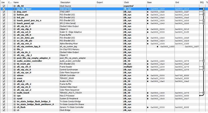
TABLE 7 QSYS CONFIGURATION OF VIP_CAMERA
The Qsys configuration contains quite a few parallel I/O ports to connect the NIOS II to some of the hardware components. The NIOS II is connected to the push buttons, I2C bus and LEDs via parallel ports. It uses just the I2C components to read in data from the camera for video processing. The buttons are also tied into some special functions such as moving the title bar when the button is pressed. These features are shown in the next section since the Qsys is primarily just creating the hardware connections.
C++ and the Main Program
Program Overview
The actual VIP_Camera program produces a video display on both the multi-touch screen and on a computer monitor via VGA. The program generates a video image using data from the camera as an input, creates it’s own title bar with a timer and displays this while accepting input from the touchscreen. The user can sit back and watch the camera feed be manipulated automatically by the program. The actual manipulation varies based on the length of time that the program has been running. The user can also play with the camera display themselves by resizing it and even “throwing” it around the screen with some simply physics effects. The bulk of the code is dedicated to creating the video image.
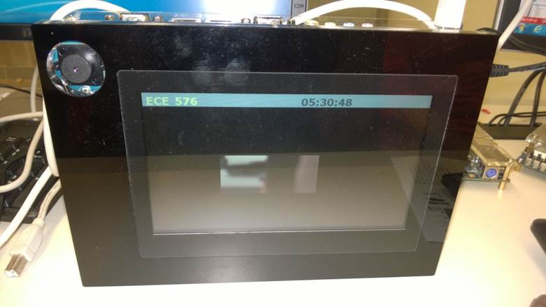
FIGURE 45 PICTURE OF VIP_CAMERA RUNNING
Video Display
The actual video display is through the path shown in the diagram in the Introduction section of the Software section of this report. The main components are the clipper, mixer, control synchronizer, scaler and frame buffers. All of these are built-in features of the Altera IP core programs. The clipper can clip out certain parts of the camera’s video feed. This is used on the camera’s feed to change what is displayed while collecting the same amount of data from it.
A similar effect is created from the scaler, which takes the camera’s video feed and changes how large or small it is displayed on the touchscreen. The scaler is automatically used when the touchscreen has no user input after a certain amount of time. It can also be trigger by the user when they touch the bottom right corner of the camera feed then either move towards the center of the video or away from it. This shows that, while the data is consistent from the camera, what’s actually displayed can be adjusted at run time.
The mixer lets you combine multiple video streams into one to display on a single screen. This is used to combine a black back layer, the camera feed and the title bar to display on the touchscreen. Each input is given a layer value when the function Mixer_set_layer_position is called and the mixer uses that to determine the order that the layers are shown on the screen. A layer with a higher number will be displayed over top of the layers of a lower number. With a layer number of 2, the title bar is always on top of the camera video feed. All of this is loaded into the frame buffer, which is then displayed on the touch screen and monitor.
With all of these different programs and effects running, the video output needs to be properly controlled. This cross-communication and collaboration is handled by a central feature called the control synchronizer. This works to ensure that as everything is being updated individually, the changes are synchronized before the video buffer is updated. This will prevent any odd effects showing up on the video from each layer updating at different.
Camera Layer Features
Within the video feed, the camera layer specifically has some special features. It uses all of the various features available with the VIP core to manipulate the camera feed. It runs in a couple different modes: automatic and user driven. The automatic mode has a fairly simple process that it walks through to show the different features. Everything is time based and it cycles through moving the camera image frame around the screen, to resizing the frame and finally zooming and panning the image.
If the user touches the touch screen, it changes the camera feed’s behavior. If the user touches near the center of the displayed image, they can move it around the screen. Moving the image and releasing it before stopping will bounce the image and it slows down until it finally stops. The edge of the camera feed can also be touched and this will resize the image. Finally, dragging to the edge of the screen will cause the image to deform against the boundary.
The majority of the features are implemented throughout the VIP core, utilizing the scaler and clipper functions. These features are implemented in move_image.c which keeps track of the camera image’s movements. It performs basic physical-like calculations to monitor the images velocity and inertia. These can be triggered manually by a user input or as part of the automatic movement routines. Below is an example screenshot of the enlarging code.
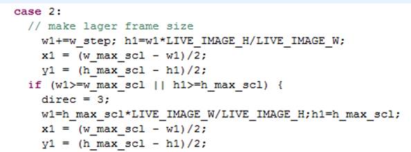
FIGURE 46 CODE SNIPPET FROM MOVE_IMAGE.C
Main Function
The main function (main.c) and move_image.c handle the bulk of the program’s user side activity. Main.c contains the functions to handle the video interrupts, touchscreen events and some of the basic parallel I/O port functions. Some are just wrapper functions like the parallel I/O functions but most implement the various activities seen on the main screen. The actual code is included in the Appendix and this section gives an overview of the process that it goes through.
Focusing just on the main procedure, it goes through all the expected setup steps. It resets and initializes the VIP cores (scaler, mixer and clip). Then is defines the display that we’re writing to by calling alt_video_display_only_frame_init with the size of the screen, color depth, buffer location and how many buffers will be used. This handles just the video feed to the screen, the touch screen response is configured by calling MTC_Init with the address and IRQ of the screen. This is also the time it calls init_i2c which, as the name implies, initializes the I2C connection to talk to the camera.
With the hardware configured, the next steps are to build up the initial display. For each of the 3 layers on the display, default parameters such as size and location are defined. Next is starts up the alarm clock routine which is the time that is being updated in the title bar. With the base parameters configured, the procedure starts up the primary components for the video by starting the control synchronizer, frame reader, clipper, scaler and mixer functions. With this, the video feed is initialized.
After performing one more interrupt routine initialization, the program enters its main loop. In the loop, it monitors the push buttons via the parallel I/O port defined in the Qsys file. The procedure is simple, it calls IORD(<address>,<register>) to read in the port’s values then grabs the first 4 bits to look for the push buttons’ states. In addition to the functions described in the Verilog code, the push buttons also have the following functions in the C++ code.
Component
|
Feature
|
KEY0
|
Move title bar up on display
|
KEY1
|
Move title bar down on display
|
KEY2
|
Add 1 hour to timer
|
KEY3
|
Add 1 minute to timer
|
TABLE 8 PUSH BUTTON KEYS AND THEIR FUNCTION IN C
Compilation
Here are some screenshots of the compilation of the code in Quartus and Eclipse. The compilation in Quartus took around 5-10 minutes on average with a powerful desktop computer and the compilation of the C++ in Eclipse was under a minute on average.
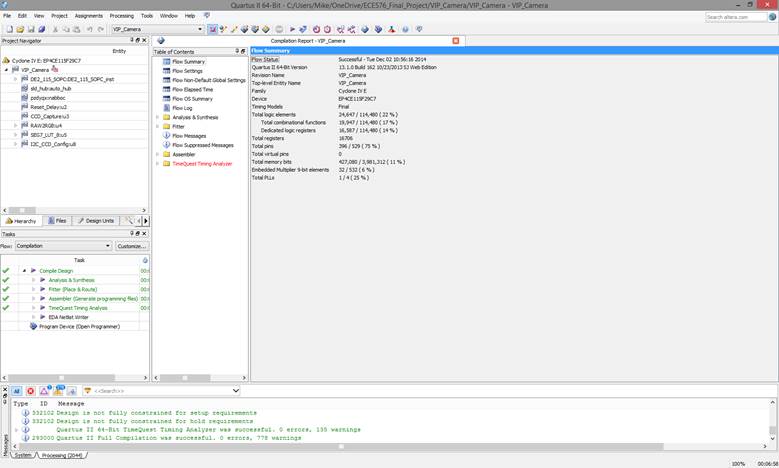
FIGURE 47 SUCCESSFUL QUARTUS II COMPILATION
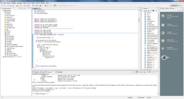
FIGURE 48 SUCCESSFUL ECLIPSE COMPILATION
Conclusion
In the proposed FPGA based digital camera with the Multi-Touch LCD, the FPGAs’ flexibility, is mainly targeting to be used as an open and low cost platform for implementing and testing real-time image processing algorithms. In addition the exploitation of LCD Touch Panel can effectively assist in the control of more camera’s parameters. Image processing algorithms can take place before or after the data storing and because of the FPGA’s presence, system has the ability to be easily modified. Future plans are to embed and test more advance image processing algorithms due to the fact that there is enough space left in the FPGA. In addition we intend to create an extended menu for the LCD touch panel. Developing such a menu the user can fully and in a friendly manner control Camera’s functionality.
Appendix
Main.c /***************************************************************************** * File: main.c for vip_demo * * This file is the top level of the vip demo. * ****************************************************************************/ #include#include #include #include #include #include #include "my_app.h" #include "my_app_gui.h" #include "alt_video_display/alt_video_display.h" #include "alt_tpo_lcd/alt_tpo_lcd.h" #include #include "system.h" #include "multi_touch.h" #include "altera_avalon_pio_regs.h" #include "audio_tvdecoder/tvdecoder_ctrl.h" #include "VIP_ctrl/vip_wrapper_for_c_func.h" #include "move_image.h" #include "my_graphics.h" #include "version_compatible.h" extern void init_i2c(); extern void move_image(int xini, int yini, int wini, int hini, int direcini); #define VFR1_SCREEN_0_BASE_ADDRESS ((int)(display->buffer_ptrs[display->buffer_being_written]->buffer)) #define VFR1_SCREEN_PIXEL_COUNT ( FRAME_BUF_W * FRAME_BUF_H) // This is our LCD display alt_video_display* display; MTC_INFO *pTouch; alt_u8 Event, TouchNum; int motion_count=0; int auto_timer=0; int title_bar_x; int title_bar_y; int title_bar_w; int title_bar_h; int pen_is_moving=0; #define ALARM_CYCLE_TIME_UPDATE 5 #define ALARM_CYCLE_FRAME_UPDATE 1 #define ALARM_CYCLE_PEN_UPDATE 10 volatile int go_time_update_flag=0; volatile int go_pen_update_flag=0; volatile int ticks=0; /*******************************************************/ volatile int time_sec=00; volatile int time_min=30; volatile int time_hour=5; alt_u32 time_alarm_callback(void * context){ go_time_update_flag = 1; ticks+=ALARM_CYCLE_TIME_UPDATE; if (ticks >= alt_ticks_per_second()){ ticks -= alt_ticks_per_second(); time_sec++; if (time_sec>=60) { time_sec = 0; time_min++; if (time_min>=60){ time_min=0; time_hour++; if (time_hour>=24) time_hour=0; } } } return ALARM_CYCLE_TIME_UPDATE; } alt_u32 pen_alarm_callback(void * context){ go_pen_update_flag = 1; return ALARM_CYCLE_FRAME_UPDATE; } int bg_col=0; set_frame_color(alt_video_display* display, int col){ vid_draw_box (0, 0, display->width, display->height, col, 1, display); } //////////////////////////////////////////////// void update_grapics(int write_all){ static int w2 = FRAME_BUF_W; static int h2 = FRAME_BUF_H; static int col_var=0; char strbuff[256]; int sw; if (write_all){ set_frame_color(display, GRAPH_BG_COL); snprintf(strbuff,256,"%s","ECE 576"); sw = vid_string_pixel_length_alpha( tahomabold_32, strbuff ); vid_print_string_alpha(10, h2/2 -32/2 -1 +0, LIGHTGREEN_24, GRAPH_BG_COL, tahomabold_32, display, strbuff); snprintf(strbuff,256,"%s",""); sw = vid_string_pixel_length_alpha( tahomabold_32, strbuff ); vid_print_string_alpha(188, h2/2 -32/2 +11 , LIGHTGREEN_24, GRAPH_BG_COL, tahomabold_20, display, strbuff); snprintf(strbuff,256,"%s",""); sw = vid_string_pixel_length_alpha( tahomabold_20, strbuff ); vid_print_string_alpha((w2-sw)-8 -2, h2/2 -20/2-4 +0 , ALTERA_COLOR2, CLEAR_BACKGROUND, tahomabold_20, display, strbuff); vid_print_string_alpha((w2-sw)-8 , h2/2 -20/2-4 +0-2, ALTERA_COLOR2, CLEAR_BACKGROUND, tahomabold_20, display, strbuff); vid_print_string_alpha((w2-sw)-8 +2, h2/2 -20/2-4 +0 , ALTERA_COLOR2, CLEAR_BACKGROUND, tahomabold_20, display, strbuff); vid_print_string_alpha((w2-sw)-8 , h2/2 -20/2-4 +0+2, ALTERA_COLOR2, CLEAR_BACKGROUND, tahomabold_20, display, strbuff); vid_print_string_alpha((w2-sw)-8 -1, h2/2 -20/2-4 +0-1, ALTERA_COLOR1, CLEAR_BACKGROUND, tahomabold_20, display, strbuff); vid_print_string_alpha((w2-sw)-8 -1, h2/2 -20/2-4 +0+1, ALTERA_COLOR1, CLEAR_BACKGROUND, tahomabold_20, display, strbuff); vid_print_string_alpha((w2-sw)-8 +1, h2/2 -20/2-4 +0-1, ALTERA_COLOR1, CLEAR_BACKGROUND, tahomabold_20, display, strbuff); vid_print_string_alpha((w2-sw)-8 +1, h2/2 -20/2-4 +0+1, ALTERA_COLOR1, CLEAR_BACKGROUND, tahomabold_20, display, strbuff); vid_print_string_alpha((w2-sw)-8 , h2/2 -20/2-4 +0 , GRAPH_BG_COL, CLEAR_BACKGROUND, tahomabold_20, display, strbuff); } snprintf(strbuff,256,"%02d:%02d:%02d", time_hour, time_min, time_sec); sw = 144; my_vid_print_string_alpha( (w2-sw)/2+ 100, h2/2 -32/2 -1 +0, col_var, GRAPH_BG_COL, tahomabold_32, display, strbuff); col_var = 255 - ticks * 2; if (col_var>255) col_var=255; col_var = (col_var<<16) | (col_var<<8) | col_var; } /*******************************************************/ /*******************************************************/ extern void pen_down( int pen_x, int pen_y); extern void pen_move( int pen_x, int pen_y); extern void pen_up( int pen_x, int pen_y); int touchscreen_event_handling(MTC_INFO *pTouch){ int pen_x; int pen_y; int pen_is_down; static int pre_pen_x; static int pre_pen_y; static int pre_pen_x1; static int pre_pen_y1; static int pre_pen_is_down; if (MTC_GetStatus(pTouch, &Event, &TouchNum, &pen_x, &pen_y, &pre_pen_x1, &pre_pen_y1)) { pen_is_down = 1; } else { pen_is_down = 0; } if ( pen_is_down ) { if (pre_pen_is_down) pen_move(pen_x, pen_y); else pen_down(pen_x, pen_y); } else if (pre_pen_is_down) { pen_up(pen_x, pen_y); } pre_pen_x = pen_x; pre_pen_y = pen_y; pre_pen_is_down = pen_is_down; usleep(15*1000); //add for mtlc return pen_is_down; } #define VIDEO_DECODER_RESET_BIT 4 static alt_u32 pio_data=0; void pio_write(alt_u32 base_addr, alt_u32 d){ pio_data = d; IOWR(base_addr,0,pio_data); } void pio_bit_set(alt_u32 base_addr, alt_u32 d){ pio_data |= d; IOWR(base_addr,0,pio_data); } void pio_bit_clr(alt_u32 base_addr, alt_u32 d){ pio_data &= ~d; IOWR(base_addr,0,pio_data); } #define VIDEO_DECODER_RESET_ON IOWR_ALTERA_AVALON_PIO_DATA(TD_RESET_PIO_BASE, 0); #define VIDEO_DECODER_RESET_OFF IOWR_ALTERA_AVALON_PIO_DATA(TD_RESET_PIO_BASE, 1); // Interrupt service routine void video_intr_task(){ Control_Synchronizer_clear_interrupt(); int touchscreen_event; // handle touch screen event if any touchscreen_event = touchscreen_event_handling(pTouch) ; // update frame size/pos variables if (! touchscreen_event){ if (auto_timer<=0) { // move by inertia { bg_col &= 0x0; // IOWR(ALT_VIP_CUSTOM_TPG_0_BASE,0,bg_col ) ; } if (motion_count==5) { free_fall_image(); } else if (motion_count==4) { move_image_top_center(-1,-1,-1,-1,-1); } else if (motion_count==3) { pan_and_scroll_image(-1,-1,-1,-1,-1); } else if (motion_count==2) { zoom_and_scroll_image(-1,-1,-1,-1,-1); } else if (motion_count==1) { move_image_center(-1,-1,-1,-1,-1); } else{ motion_count=0; move_image(-1,-1,-1,-1,-1); } bounce_image_reset(); } else { bounce_image(); } } { set_hw(); // Set HW parameters and wait for next interrupt } } ///////////////////////////////////////////////////////////////////////////// int main() { //VIDEO_DECODER_RESET_ON; // reset TV Decoder chip // Stop VIP cores Clipper_stop(0); Scaler_stop(0); Mixer_stop(0); //int rv; printf("\n\n\n\n"); printf("**********************************************************\n"); printf("* VIP DEMO LCD_SVGA version rev.1 has been started! *\n"); printf("**********************************************************\n\n"); display = alt_video_display_only_frame_init( FRAME_BUF_W, // int width FRAME_BUF_H, // int height ALT_VIDEO_DISPLAY_COLOR_DEPTH, // int color_depth SDRAM_BASE + 0x00800000, // int buffer_location 1 ); // int num_buffers if (display == NULL){ printf("Memory Alloc error !\n"); while(1){} } // a debug message printf("go\n"); // set hardware adderss of I2C port init_i2c(); printf("\n"); //initial MULTI-touch pTouch = MTC_Init(MULTI_TOUCH_BASE, MULTI_TOUCH_IRQ); if (!pTouch){ printf("Failed to init multi-touch\r\n"); }else{ printf("Init touch successfully\r\n"); } bg_col = 0x24888444; IOWR(ALT_VIP_CUSTOM_TPG_0_BASE,0,bg_col); // LCD display area size int w_max=LCD_DISPLAY_W; int h_max=LCD_DISPLAY_H; // Live image default size/pos int w1 = LIVE_IMAGE_W; int h1 = LIVE_IMAGE_H; int x1 = (w_max - w1)/2; int y1 = (h_max - h1)/2; // NiosII default size/pos title_bar_w = FRAME_BUF_W; title_bar_h = FRAME_BUF_H; title_bar_x = (w_max - title_bar_w)/2; title_bar_y = 0; // Set up Nios II frame buffer background color set_frame_color(display, GRAPH_BG_COL); // Start alarm for Clock display function alt_alarm alarm_time_update; if (alt_alarm_start(&alarm_time_update, ALARM_CYCLE_TIME_UPDATE, time_alarm_callback, NULL) < 0 ){ printf("No system Clock\n"); } Control_Synchronizer_init(); Frame_Reader_init(); Frame_Reader_set_frame_0_properties( VFR1_SCREEN_0_BASE_ADDRESS, VFR1_SCREEN_PIXEL_COUNT, VFR1_SCREEN_PIXEL_COUNT, FRAME_BUF_W, FRAME_BUF_H, 3); // 3=progressive video Frame_Reader_switch_to_pb0(); Frame_Reader_start(); // Start VIP Cores Clipper_init(); Scaler_init(); Mixer_init(); //Mixer_set_layer_position(0, 0, 80); Mixer_set_layer_position(1, x1, y1); Scaler_set_output_size( w1, h1); Mixer_set_layer_position(2, title_bar_x, title_bar_y); move_image(x1, y1, w1, h1, 1); update_grapics(1); // debug message printf("ok1\n"); int button=0xf; int loop_cnt=0; int pre_time_sec=-1; alt_ic_isr_register(0, ALT_VIP_CTS_0_IRQ, video_intr_task, NULL, NULL); set_hw(); while(1) { // update Nios II frame if(go_time_update_flag) { // update Nios II frame update_grapics(0); // for debug if(pre_time_sec != time_sec){ if (button == 0xe) { // debug print // int ad=0x10; // printf("lp:%d, ADV7180[%02x]=0x%02x \n",loop_cnt, ad, tv_decoder_read(ad)); } loop_cnt=0; pre_time_sec = time_sec; } go_time_update_flag=0; if (auto_timer>0) auto_timer -= ALARM_CYCLE_TIME_UPDATE; } // push button handling button = IORD(BUTTON_PIO_BASE,0) & 0xf; if (button != 0xf) { switch (button) { case 0xd : title_bar_y+=4; if( title_bar_y > (h_max - FRAME_BUF_H) ) title_bar_y = (h_max - FRAME_BUF_H); Mixer_set_layer_position(2, title_bar_x, title_bar_y); usleep(1000*5); break; case 0xe : title_bar_y-=4; if (title_bar_y<0) title_bar_y=0; Mixer_set_layer_position(2, title_bar_x, title_bar_y); usleep(1000*5); break; case 0x7 : time_min++; if (time_min>59) time_min = 0; update_grapics(0); usleep(1000*200); break; case 0xb : time_hour++; if (time_hour>23) time_hour = 0; update_grapics(0); usleep(1000*200); break; } } } // end of while(1) loop return ( 0 ); } Move_image.c /***************************************************************************** * File: move_image.c * * This file is the top level of the application selector. * * Control Scaler and Clipper and Mixer ****************************************************************************/ #include "move_image.h" //#include


沒有留言:
張貼留言