LFSR 線性回授暫存器 以G(x )=x^4+x+1為例
初始值不可設為0 否則無法產生虛擬亂數 (還是有週期性)


// Ch08 lfsr.v
// 線性回授移位暫存器 //1+x+x^4 LFSR Eq.
module LFSR (SW, LEDR, LEDG , CLOCK_50,CLOCK_27 ,KEY
,HEX0 ,HEX1 ,HEX2,HEX3 ,HEX4 );
input [17:0] SW; // toggle switches
input [3:0] KEY; // Push bottom
input CLOCK_27; //Clock 27MHz
input CLOCK_50; //Clock 50MHz
output [17:0] LEDR; // red LEDS
output [7:0] LEDG; // green LEDs
output [6:0] HEX0,HEX1,HEX2,HEX3 ,HEX4; //7-segment display
//set original program input , output
//lfsr (Clk,Clr,Q);
//input Clk,Clr; // 一位元輸入
//output [3:1] Q; // 3位元輸出
//reg [3:1] Q; // 宣告為暫存器資料
reg [4:1] Q = 4'b0001; // 宣告為暫存器資料
wire HZ_1; //1HZ Clock
wire Clr;
wire [7:0] segout0; //HEX 0
assign Clr=KEY[0];
//module _1HZ (CLK, RSTn, LED_Out);
_1HZ UUT01
(.CLK(CLOCK_50),
.RSTn(Clr),
.LED_Out(HZ_1));
// 上緣觸發時脈,上緣同步清除
always@ (posedge HZ_1 or negedge Clr )
begin
if (!Clr)
Q = 4'b0001;
else
Q = {Q[3:2],Q[4]^Q[1],Q[4]}; //1+x+x^4 LFSR Eq.
end
//_7seg UUT0(.hex({Q[1],Q[2],Q[3],Q[4]}),
// .seg(segout0));
_7seg UUT0(.hex(Q),
.seg(segout0));
assign HEX0=segout0[6:0];
assign LEDG[3:0]=Q;
//assign LEDG[3:0]={Q[1],Q[2],Q[3],Q[4]};
endmodule
/*
// Ch08 lfsr.v
// 線性回授移位暫存器 1+x+x^3
module lfsr (Clk,Clr,Q);
input Clk,Clr; // 一位元輸入
output [3:1] Q; // 三位元輸出
reg [3:1] Q; // 宣告為暫存器資料
// 上緣觸發時脈,上緣同步清除
always@ (posedge Clk)
if (Clr)
Q = 3'b100;
else
Q = {Q[2:1],Q[1] ^ Q[3]};
endmodule
*/
//====================================
//Clock input 50MHZ
//====================================
module _1HZ (CLK, RSTn, LED_Out);
input CLK;
input RSTn;
output LED_Out;
/*************************************/
parameter T1S = 24'd50_000_000; //50MHZ
/*************************************/
reg [23:0]Count1;
always @ ( posedge CLK or negedge RSTn )
begin
if( !RSTn )
Count1 <= 24'd0;
else if( Count1 == T1S )
Count1 <= 24'd0;
else
Count1 <= Count1 + 1'b1;
end
/*************************************/
reg rLED_Out;
always @ ( posedge CLK or negedge RSTn )
begin
if( !RSTn )
rLED_Out <= 1'b0;
else if( Count1 >= 24'd0 && Count1 < 24'd25_000_000 )
//0.5sec ON , o.5sec OFF
rLED_Out <= 1'b1;
else
rLED_Out <= 1'b0;
end
/***************************************/
assign LED_Out = rLED_Out;
/***************************************/
endmodule
//-----------------------------------------
//Common-cathod seven segment display
//using case.....endcase statement
//Filename : sevenseg_case.v
//-----------------------------------------
module _7seg(hex , seg);
input [3:0] hex;
output [7:0] seg;
reg [7:0] seg;
// segment encoding
// 0
// ---
// 5 | | 1
// --- <- 6
// 4 | | 2
// ---
// 3
always @(hex)
begin
case (hex)
// Dot point is always disable
4'b0001 : seg = 8'b11111001; //1 = F9H
4'b0010 : seg = 8'b10100100; //2 = A4H
4'b0011 : seg = 8'b10110000; //3 = B0H
4'b0100 : seg = 8'b10011001; //4 = 99H
4'b0101 : seg = 8'b10010010; //5 = 92H
4'b0110 : seg = 8'b10000010; //6 = 82H
4'b0111 : seg = 8'b11111000; //7 = F8H
4'b1000 : seg = 8'b10000000; //8 = 80H
4'b1001 : seg = 8'b10010000; //9 = 90H
4'b1010 : seg = 8'b10001000; //A = 88H
4'b1011 : seg = 8'b10000011; //b = 83H
4'b1100 : seg = 8'b11000110; //C = C6H
4'b1101 : seg = 8'b10100001; //d = A1H
4'b1110 : seg = 8'b10000110; //E = 86H
4'b1111 : seg = 8'b10001110; //F = 8EH
default : seg = 8'b11000000; //0 = C0H
endcase
end
endmodule
The pseudo-random sequence is generated by a linear feedback shift register (see diagram). The serial data enters the LFSR, where each stage is a D-type flip-flop equivalent to one time unit of delay. The delayed signal is tapped, with XOR (modulo-2) feedback with the input signal. For the descrambler, the XOR process is feed-forward.
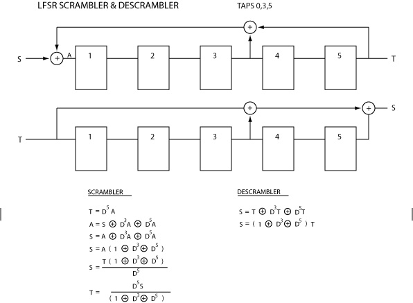
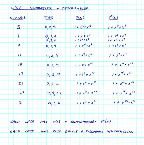
Linear feedback shift registers are often expressed in polynomial form. The table below lists the polynomial representations of a number of LFSRs. Certain combinations of taps are preferred to give maximal sequence length (see table).
The previous diagram shows an n = 5 stage self-synchronizing scrambler/descrambler, implemented using LFSRs. For an n-bit LFSR, these will resynchronize after n bits if the scrambler and descrambler become desynchronized due to bit errors. A slight disadvantage is that each bit error is multiplied by the number of taps used by the LFSR (typically 3).
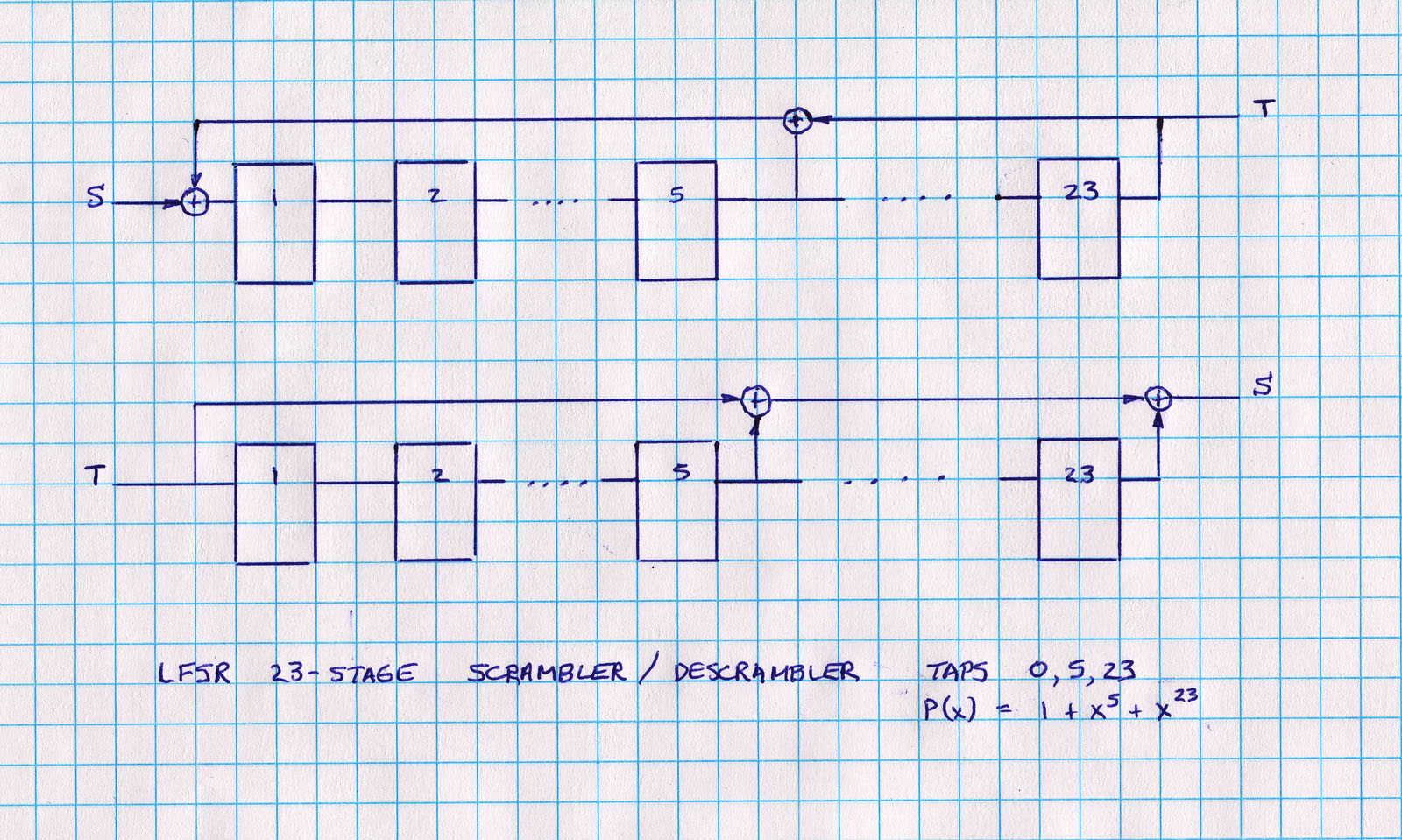
Some input data sequences to the LFSR can result in undesirable side effects. For instance, if the LFSR gets into an all-zero state, it will stay stuck in that state (so-called killer packet problem). The problem can be minimized by using a longer LFSR (say n>23), or adding logic to detect and correct the all-zeros state.
For most input sequences, the output of the scrambler will appear to be a random sequence of 1s and 0s, with a 0.5 probablility of each. That is, the output will be DC balanced. In addition, the output sequence will have a high density of transitions which are essential for clock recovery.

The figure shows the 'impulse response' of feeding a logic 1, followed by zeros to a 23-stage scrambler. After an initial delay of 23 clock cycles, the output (TXD) is randomized while the input (SDATA) is all zeros.
In EPLD terms, the following is the representation of a 23-stage scrambler/descrambler codes using Altera megafunctions in verilog. Note that the shift register numbering starts at 0, where the tap numbering for LFSRs normally starts at 1 (the reader can work out the correspondence).


沒有留言:
張貼留言