4bits Binary Up-Down Counter
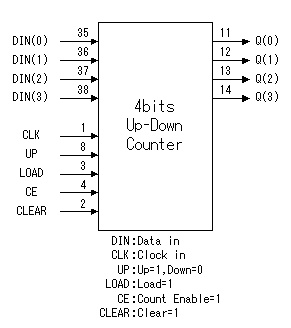
On this page, I will introduce "4 bits Binary Up-Down Counter" which was written in VHDL.
This source file is written for CPLD(XC9536-PC44). The other CPLD device can be used if arranging a little. The logic is the function which is same as Logic IC( 74161 ) approximately. But, a carry bit, a borrow bit aren't supported. Those functions can be put if you arrange logic. I programed this logic in CPLD and confirmed in the operation and had confirmed normal operation.
| ||||||||||||||||||||||||||||||||||||||||||||||||
// Ch08 cnt1.v
// 上數與下數計數器
module cnt1 (SW, LEDR, LEDG , CLOCK_50,CLOCK_27 ,KEY
,HEX0 ,HEX1 ,HEX2,HEX3 ,HEX4 );
input [17:0] SW; // toggle switches
input [3:0] KEY; // Push bottom
input CLOCK_27; //Clock 27MHz
input CLOCK_50; //Clock 50MHz
output [17:0] LEDR; // red LEDS
output [7:0] LEDG; // green LEDs
output [6:0] HEX0,HEX1,HEX2,HEX3 ,HEX4; //7-segment display
//set original program input , output
//(Clk,Clr,Q1,Q2);
//input Clk,Clr; // 一位元輸入
//output [3:0] Q1,Q2; // 四位元輸出
//reg [3:0] Q1,Q2; // 宣告為暫存器資料
reg [3:0] Q1,Q2; // 宣告為暫存器資料
wire HZ_1; //1HZ Clock
wire Clr;
wire [7:0] segout0; //HEX 0
wire [7:0] segout1; //HEX 1
assign Clr=KEY[0];
//module _1HZ (CLK, RSTn, LED_Out);
_1HZ UUT01
(.CLK(CLOCK_50),
.RSTn(Clr),
.LED_Out(HZ_1));
// 上緣觸發時脈, 上緣同步清除, 上數計數器
always@ (posedge HZ_1 or negedge Clr )
begin
if (!Clr) Q1 = 0;
else Q1 = Q1 + 1;
end
// 上緣觸發時脈, 上緣同步清除, 下數計數器
always@ (negedge HZ_1 or negedge Clr )
begin
if (!Clr) Q2 = 15;
else Q2 = Q2 - 1;
end
_7seg UUT0(.hex(Q1),
.seg(segout0));
_7seg UUT1(.hex(Q2),
.seg(segout1));
assign HEX0=segout0[6:0];
assign HEX1=segout1[6:0];
assign LEDG[3:0]=Q1;
assign LEDR[3:0]=Q2;
endmodule
/*
// Ch08 cnt1.v
// 上數與下數計數器
module cnt1 (Clk,Clr,Q1,Q2);
input Clk,Clr; // 一位元輸入
output [3:0] Q1,Q2; // 四位元輸出
reg [3:0] Q1,Q2; // 宣告為暫存器資料
// 上緣觸發時脈, 上緣同步清除, 上數計數器
always@ (posedge Clk)
if (Clr) Q1 = 0;
else Q1 = Q1 + 1;
// 上緣觸發時脈, 上緣同步清除, 減二下數計數器
always@ (posedge Clk)
if (Clr) Q2 = 15;
else Q2 = Q2 - 2;
endmodule
*/
//-----------------------------------------
//Common-cathod seven segment display
//using case.....endcase statement
//Filename : sevenseg_case.v
//-----------------------------------------
module _7seg(hex , seg);
input [3:0] hex;
output [7:0] seg;
reg [7:0] seg;
// segment encoding
// 0
// ---
// 5 | | 1
// --- <- 6
// 4 | | 2
// ---
// 3
always @(hex)
begin
case (hex)
// Dot point is always disable
4'b0001 : seg = 8'b11111001; //1 = F9H
4'b0010 : seg = 8'b10100100; //2 = A4H
4'b0011 : seg = 8'b10110000; //3 = B0H
4'b0100 : seg = 8'b10011001; //4 = 99H
4'b0101 : seg = 8'b10010010; //5 = 92H
4'b0110 : seg = 8'b10000010; //6 = 82H
4'b0111 : seg = 8'b11111000; //7 = F8H
4'b1000 : seg = 8'b10000000; //8 = 80H
4'b1001 : seg = 8'b10010000; //9 = 90H
4'b1010 : seg = 8'b10001000; //A = 88H
4'b1011 : seg = 8'b10000011; //b = 83H
4'b1100 : seg = 8'b11000110; //C = C6H
4'b1101 : seg = 8'b10100001; //d = A1H
4'b1110 : seg = 8'b10000110; //E = 86H
4'b1111 : seg = 8'b10001110; //F = 8EH
default : seg = 8'b11000000; //0 = C0H
endcase
end
endmodule
//====================================
//Clock input 50MHZ
//====================================
module _1HZ (CLK, RSTn, LED_Out);
input CLK;
input RSTn;
output LED_Out;
/*************************************/
parameter T1S = 24'd50_000_000; //50MHZ
/*************************************/
reg [23:0]Count1;
always @ ( posedge CLK or negedge RSTn )
begin
if( !RSTn )
Count1 <= 24'd0;
else if( Count1 == T1S )
Count1 <= 24'd0;
else
Count1 <= Count1 + 1'b1;
end
/*************************************/
reg rLED_Out;
always @ ( posedge CLK or negedge RSTn )
begin
if( !RSTn )
rLED_Out <= 1'b0;
else if( Count1 >= 24'd0 && Count1 < 24'd25_000_000 )
//0.5sec ON , o.5sec OFF
rLED_Out <= 1'b1;
else
rLED_Out <= 1'b0;
end
/***************************************/
assign LED_Out = rLED_Out;
/***************************************/
endmodule


沒有留言:
張貼留言