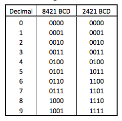
Design an 8421 BCD to 2421 BCD converter circuit. The truth table as follows:

Note that input combinations of 1010 to 1111 can be treated as "don't cares".
//verilog operator
//Operator Type
// & And
// ~& Nand
// | Or
// ~| Nor
// ^ Xor
// ~^ Xnor
module bcd_2421(A,B,C,D, x,y,z,t);
input A,B,C,D ; // A,B,C,D 1位元輸入
output x,y,z,t ; // Output 1位元輸出
reg x,y,z,t;
always@(A or B or C or D)
begin
x = ((B&C) | (B&D) | A);
y = ( A | (B&~D) | (B&C) );
z = ( A | (~B&C) | (B&~C&D));
t = D;
end
endmodule
// 時間單位 100ns, 時間精確度100 ps
`timescale 100ns/100ps
module Test_bench;
reg t_A,t_B,t_C,t_D = 1'b0; // 暫存器資料初值為‘0’
wire t_x,t_y,t_z,t_t;
integer i;
bcd_2421 DUT( .A(t_A),.B(t_B),.C(t_C),.D(t_D),.x(t_x),.y(t_y),.z(t_z),.t(t_t) );
// initial程序結構區塊, 產生A、B輸入信號波形
initial begin
$monitor({t_A,t_B,t_C,t_D},{t_x,t_y,t_z,t_t});
for (i=0; i<16; i=i+1) begin
{t_A,t_B,t_C,t_D} = i;
#20;
end
end
initial
begin
#340; // 模擬終止時間 200 ns
$stop;
end
endmodule


沒有留言:
張貼留言