Combinational circuits using Decoder
For example, if we need to implement the logic of a full adder, we need a 3:8 decoder and OR gates. The input to the full adder, first and second bits and carry bit, are used as input to the decoder. Let x, y and z represent these three bits. Sum and Carry outputs of a full adder have the following truth tables-

Therefore we have-


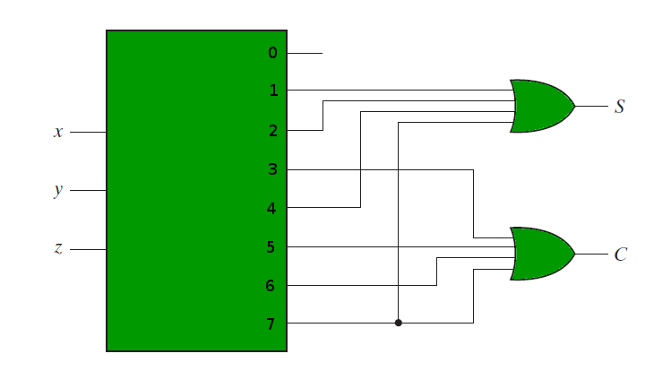
The following circuit diagram shows the implementation of Full adder using a 3:8 Decoder and OR gates.
Therefore we have-
The following circuit diagram shows the implementation of Full adder using a 3:8 Decoder and OR gates.


module SOP_decoder_FullAdder(a,b,cin,Sum,Cout);
input a,b,cin;
output Sum,Cout;
wire d0,d1,d2,d3,d4,d5,d6,d7;
assign d0=(~a&~b&~cin);
assign d1=(~a&~b&cin);
assign d2=(~a&b&~cin);
assign d3=(~a&b&cin);
assign d4=(a&~b&~cin);
assign d5=(a&~b&cin);
assign d6=(a&b&~cin);
assign d7=(a&b&cin);
assign Sum= d1 | d2 | d4 | d7;
assign Cout = d3 | d5 | d6 | d7;
endmodule
// 時間單位 100ns, 時間精確度100 ps
`timescale 100ns/100ps
module Test_bench;
reg a,b,cin = 1'b0; // 暫存器資料初值為‘0’
wire Sum,Cout;
integer i;
//SOP_decoder_FullAdder(a,b,cin,Sum,Cout);
SOP_decoder_FullAdder UUT(.a(a),.b(b),.cin(cin),.Sum(Sum),.Cout(Cout));
// initial程序結構區塊, 產生輸入信號波形
initial begin
$monitor(a,b,cin,Sum,Cout);
for (i=0; i<8; i=i+1) begin
{a,b,cin} = i;
#20;
end
end
initial
begin
#160; // 模擬終止時間 160 ns
$stop;
end
endmodule


沒有留言:
張貼留言