https://alselectro.wordpress.com/2016/06/27/home-automation-iot-demo-with-esp8266-wifi-iot-test-board/
Home Automation–IOT Demo with ESP8266 WiFi IOT Test Board
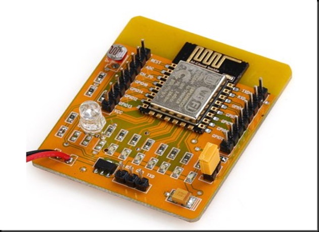
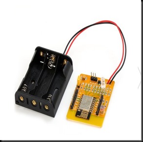
Introducing a new ESP8266 Development Board with an ESP-12, a 3x AA battery holder, a voltage regulator, an RGB LED, several red LEDs, and a light sensor LDR on the ADC input all on one board.
The board can be controlled by an open source Android App which is available from the AI-THINKER Website.
GPIO pins are extended with berg pins for easy external connections. RXD,TXD & GND pins are provided for programming / firmware upgrading. A yellow jumper is provided to pull GPIO0 pin to GND during programming. During normal operation this jumper must be removed.
The board is powered by 3 nos AA batteries , for which a battery box is already wired. On board 3.3v regulator is provided for a stable power supply.
No power switch or Reset switch is provided. To switch off you need to pull out one of the batteries.
The board comes pre-loaded with a demo which does actually seem to work. If you have an Android based phone or tablet you can download AI-Thinker’s app to control and mix the color balance on the RGB LED and to switch the other LEDs on and off.
The Android Application can be downloaded from :
There are also 6 red LEDs fixed with the necessary resistors connected to GPIO16, GPIO14, GPIO5, GPIO4, GPIO0 and GPIO2. A BLUE LED is always ON if the board is powered.
The GPIO13, GPIO12 and GPIO15 are connected to a RGB LED which allows you color mixing using PWM.
ADC
The analog-digital converter is also available on a pin & connected to a light resistor. This lets you quickly test the ADC and you still can clip the resistor off if you want to measure another analog source.Remember the range of ADC is max 1v & not 0 to 3.3v
If you don’t want to use the light sensor or the LEDs you can simply clip them off. Then you’ll just have an ESP8266 with 3xAA power supply, 9 available GPIO pins and one ADC.
On the playstore of your Android device search for IOT DEMO App & install it.
Open the Settings & enable WIFI of the Android phone.Now power on the ESP board to see the AI-THINKER SSID on your mobile.
PAIR this with the ESP board using password ai-thinker
Now open the app & touch on LED 1 to 6 , to see the corresponding light glowing on the ESP board.Onthe top you can see 3 icons with sliders in the App. Use this to mix colors on the 3 color LED of ESP board.
Once the functioning of board is verified , you can proceed to connect the GPIO pins of ESP board with a 4 channel Relay board.
The 4 channel relay board used requires a separate power source of 5V, 1amp.For demo 2 of the GPIO pins are connected to relay 1 & relay 3.The GND pins of both ESP & the Relay. board to be made common.
You can watch this video to learn the home automation basics with ESP board :


沒有留言:
張貼留言