https://alselectro.wordpress.com/category/bluetoothwifi/1
ESP8266 WIFI Module comes with an inbuilt firmware which supports serial interface and can be controlled using AT commands. Even though we can use this module to offer WiFi functionality from another micro controller ,this module is not just a simple serial to WiFi transceiver .
It is comprised of a 32Bit processor ( 80MHz) , 512KB SPI FLASH , 64KB SRAM ,96KB DRAM , GPIO Pins & WIFI Transceiver.
In this post I shall walk you through how to upgrade new Firmware on to the ESP module.Thisprocedure can also be followed in case esp8266 stopped working , or giving out some random garbage data.
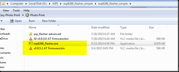
Before starting upgrading I downloaded following 2 files .
1. ESP SIMPLE FLASHER – FLASH DOWNLOAD TOOL
2. FIRMWARE latest BIN file version 9.5.0
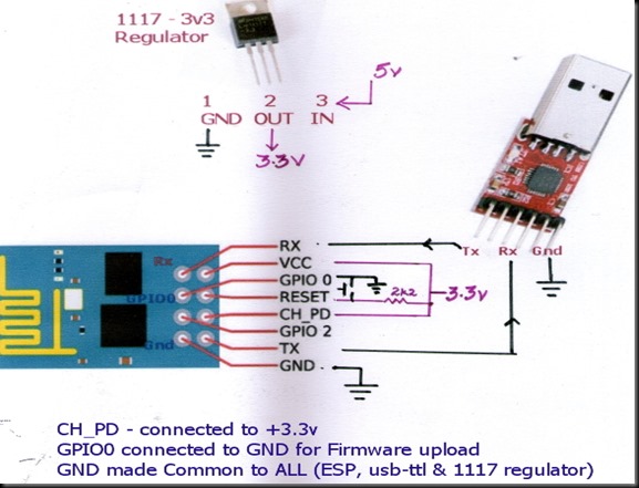
I used a USB – TTL converter between my ESP-01 board & PC. As the ESP device requires 200ma current which cannot be sourced from USB-TTL module , I used a separate power source 5v/1Amp adaptor followed by a 3.3v regulator ( 1117 3.3v).
Please note that while I used a separate power source for ESP module , the operation was smooth.
I connected the ESP module with USB-TTL board as per following wiring diagram :
CH-PD is CHIP ENABLE which is directly connected to +3.3v
RST is pulled HIGH through a 2k2 resistor.A press switch is connected to GND , so that when it is pressed RST pin is grounded.
TX of ESP is connected to RX of USB-TTL module
RX is connected to TX .
Vcc is connected to +3.3v of the external Regular. GND is made common for all , i.e GND of ESP ,USB-TTL & that of 1117 regulator are ALL MADE COMMON.
GPIO0 pin is connected to GND to upload firmware.
After uploading firmware , this GPIO0 connection must be removed from GND.
The USB-TTL converter I used is built on Silicon Labs CP2102 chip which is highly reliable one.Theother type available in the market is built on Prolific chip (Chinese one , not original) , which has got some issues with driver installation .
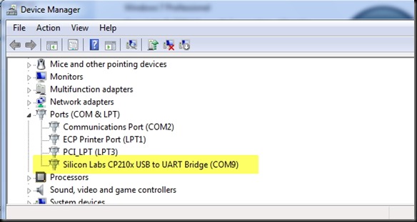
I connected the USB-TTL board to my PC & from the Device Manager I noted the Port allotted .
COM port COM9 is allotted.
Next , I browsed to the folder where I’ve already downloaded the 2 required files , one is the simple flasher & the other one is the latest firmware to be uploaded.
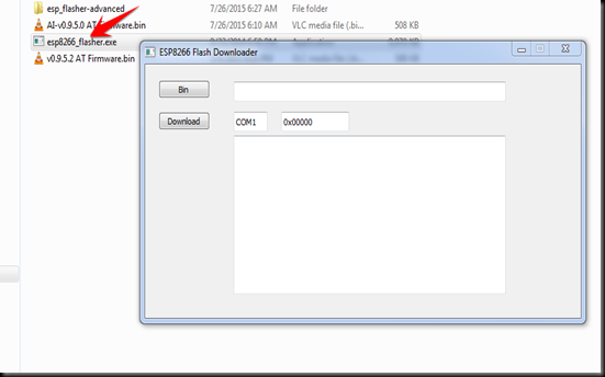
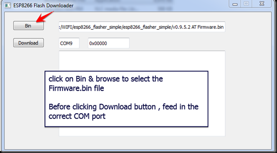
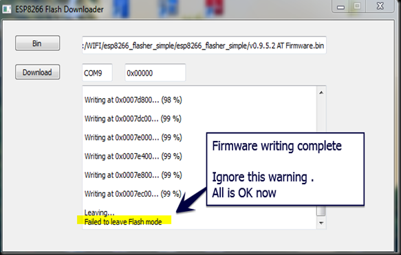
On double clicking the esp8266_flasher .exe file , I got this Downloader window open
I clicked on the BIN button & browsed to the location of the folder to select firmware.bin file.
Before clicking the DOWNLOAD button I changed the COM port number , where USB-TTL is connected to PC.
The default address 0x000000 is automatically displayed after COM port
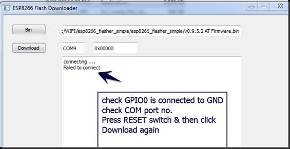
First time when I clicked the Download button I got “Failed to connect” error.
This was because I’ve connected GPIO0 to GND after the power to ESP board is ON.
GPIO0 pin must be at GND level when the power is initially provided to the ESP module.
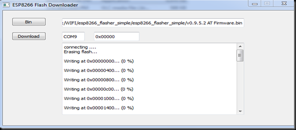
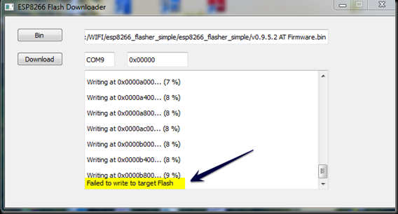
Second time when I clicked on the Download button , Writing started but abruptly failed .
You can see the “Failed to write to target Flash” message in the screenshot below .
After repeated trials I finally found that , connecting 100uf capacitor between Vcc & Gnd
solved the problem.
Finally I hit the Download button and waited for the flashing process to complete. The STATUS BLUE LED blinked fast while the uploading was going on.
“ Failed to leave Flash mode “ message after 99% writing ,does not affect the flashing process in any way and can be ignored.
After the firmware flashing, ESP8266 module settings changed. The default baud rate now is 9600 & can be modified using AT+CIOBAUD command.
It is even possible to cloud update ESP8266 Wi-Fi module firmware using AT+CIUPDATE command.ButI suggest you not to try this cloud update , as it’s got some issues.
Now I removed GPIO0 pin from GND & pressed RESET switch & then closed the Flasher application.
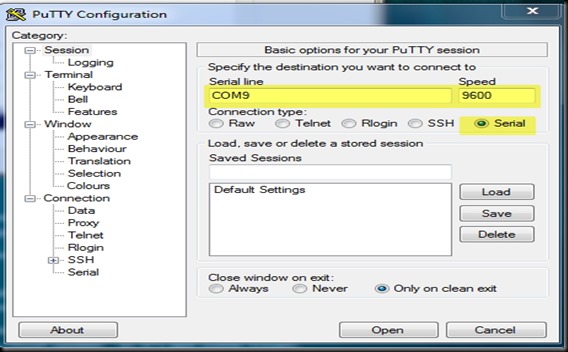
I opened the terminal software Putty & selected Serial COM Port 9 & baud rate 9600.
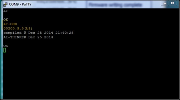
I typed in AT command & got an OK response from the ESP module.
AT+GMR returned the upgraded firmware version 9.5.
Watch this support Video :


沒有留言:
張貼留言