https://alselectro.wordpress.com/2016/11/07/esp8266-upload-code-from-arduino-ide-no-arduino-board-required/
ESP8266 – Upload code from Arduino IDE – No Arduino Board Required
The ESP8266 by itself hosts a 32 bit Microcontroller on it & you can now program your ESP using Arduino IDE. Best part is that NO Arduino board is required.You can upload your code from Arduino IDE , as if you were upgrading the Firmware on ESP.
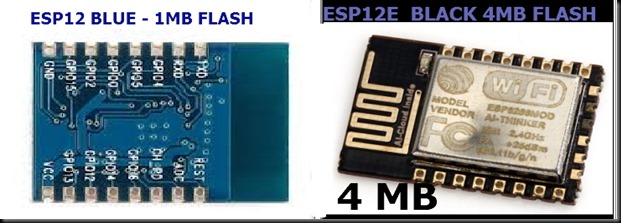
You can pretty much write any code for an Arduino and run it on the ESP8266. Of course there is a limit to the I/O on some of the modules, but the Flash on the ESP-12E (Black) module is 4MB and the RAM is 80kB! Add to that the 80MHz 32-bit processor and you have a pretty impressive little cute Arduino.
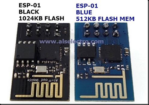
A sample Blink example program on the ESP8266 turns out to be around 225kB, but that includes the core code.So it’s advisable to use an ESP8266 with more FLASH Memory.Generally the BLACK ones are with higher memory than the Blue ones.The new ESP12E has a Flash of whooping 4MB !! The Arduino UNO has just 32k Flash & Mega 256k.
Program uploading is done at 115,200 Baud, the default for the module. But It still takes a while to upload a sketch to the module , unlike a regular Arduino.
To begin, you must install the ESP8266 board files in the Arduino IDE.
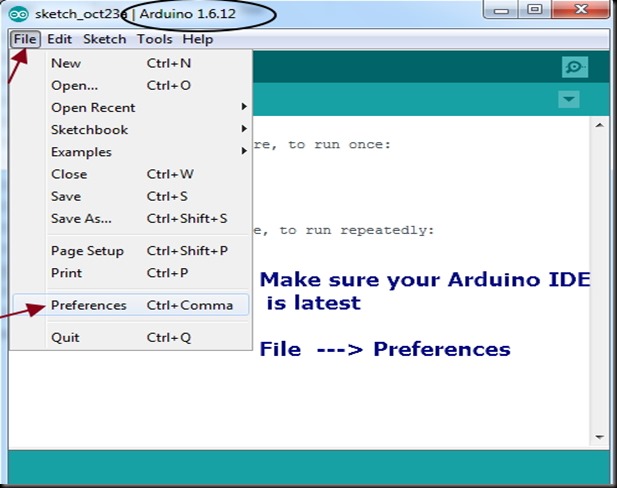
That is easy enough to do. Make sure that your Arduino IDE is latest
Open the Arduino preferences from File —> Preferences
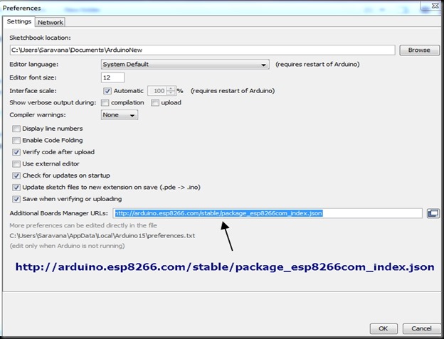
Add the following URL to the “Additional Boards Manager URLs” seen at the bottom of Preferences Window
Click OK to close the Preferences Window.
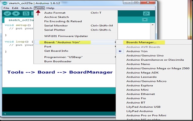
Click on TOOLS –. BOARDS—> BOARDS MANAGER
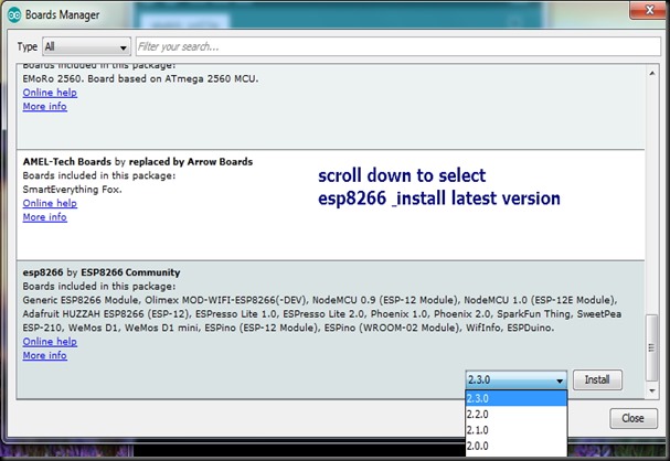
When the Boards Manager opens, scroll to the bottom. You should see the esp8266 entry.
Select the latest version & then click on INSTALL button.
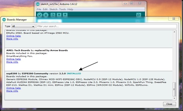
It takes a while to download & install .
Once installation is over , close the IDE & start again,
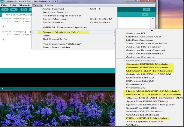
Under Tools –> Boards you can now see a new list of ESP8266 Modules.
Its time to test some example code.
While using the ESP module make sure that
Power source is 3.3v DC
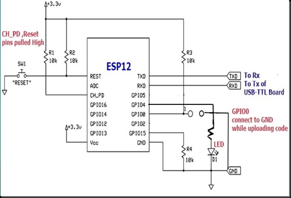
CH_PD & RESET pins pulled HIGH through resistor.
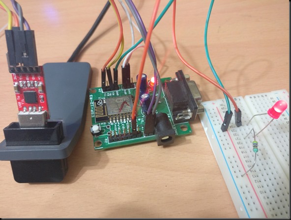
You can use a development board available at
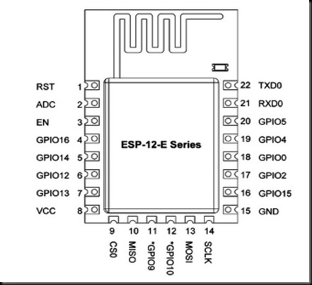
An LED is connected to GPIO4 through a resistor.
An USB-TTL board is used to connect ESP with USB port of PC.
Rx of USB-TTL board goes to Tx of ESP board
Tx of USB-TTL goes to Rx (3.3v level) of ESP board
GND is made common.
5v of USB-TTL is connected to Vcc of ESP board.As the ESP board has a built in 3.3v regulator we can connect to 5v safely.
Connect the GPIO0 pin to GND.
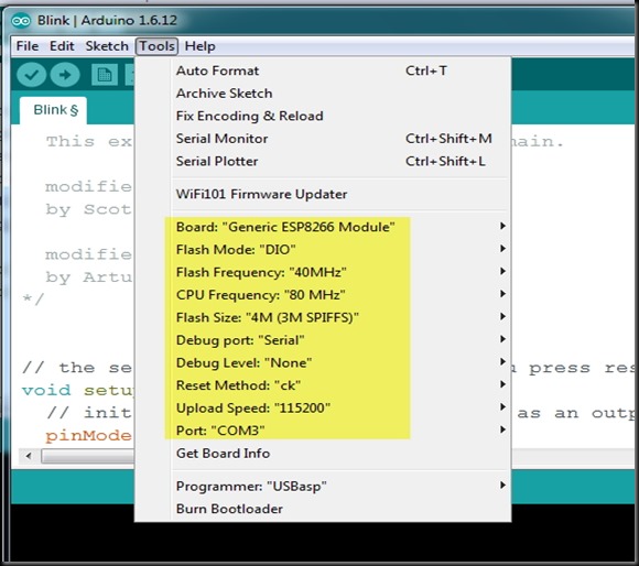
Open the Arduino IDE & select the COM port allotted to the USB-TTL board.
Other settings are done under Tools tab as seen in screenshot below :
From File —> Examples —> ESP8266 select the BLINK sketch.
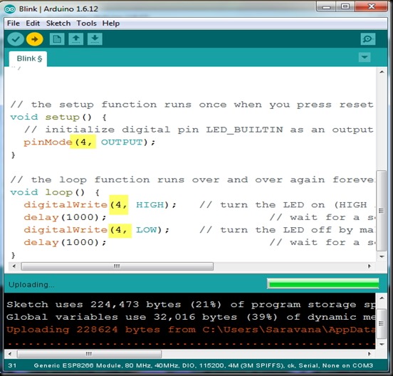
As we’ve connected an LED at GPIO4 pin , change the pinMode & digitalWrite pin to 4.
Ensure that GPIO0 is connected to GND & click on UPLOAD button.
It takes a while to compile & then uploading starts.
Once the Uploading is done the LED connected at pin 4 , starts blinking.
Remember to upload another sketch, you need to ground GPIO0 and push the reset switch. The ESP8266 will be put in UPLOAD mode.
When the upload is done, the sketch will start running. If you reset with GPIO0 still grounded, the sketch will not start running because the ESP8266 will be in PROGRAMMING mode. To exit programming mode, remove the ground from GPIO0.
WATCH THIS VIDEO :
In the next post we shall see how to use the built in WIFI library in your code.


沒有留言:
張貼留言