https://alselectro.wordpress.com/category/bluetoothwifi/ˇ
It is quite simple to pair a Bluetooth module from your Android phone.But bit tricky to pair it with another HC-05 module.In this post I’ll describe the method of pairing 2 BT modules.One of the module is assigned ROLE as MASTER & the other left as SLAVE.
By default all HC05 modules are SLAVEs.Using AT commands the module can be configured as we like.
To configure the SLAVE we make use of an Arduino UNO board.Not much of configuration needed for slave.We can leave it to defaults.But to know the ADDRESS of the slave you’ve to follow this procedure.

Before connecting the HC05 module , upload an empty sketch to Arduino. This bypasses the Boot loader of UNO & the Arduino is used as USB-UART converter.
void setup() {}
void loop() {}
After uploading this empty sketch,remove USB power from Arduino & do the following connections with HC05 Slave :
——————————————-
ARDUINO HC05
Rx(pin0 ) —> Rx Remember it is one to one connection here & not cross connection
Tx (pin1) —-> Tx
+5v ——-> VCC
GND ——-> GND
+3.3V ——–> KEY
————————————————-
Now provide the USB cable power to Arduino.The HC05 module enters the Command mode with Baud Rate 38400.
Open the Serial Monitor of Arduino .
Ensure to select “BOTH NL & CR” & Baud Rate as 38400 at the bottom of the serial monitor.This is very important as the Bluetooth module HC05 expects both Carriage Return and Line Feed after every AT command.

If you type in AT & click on SEND button you should get an OK confirmation from the HC05 module.
If you get ERROR(0) try again to enter the Command mode.If there is no response then check whether correct COM port has been assigned in Arduino IDE & confirm Baud Rate is 38400 , “Both NL & CR” selected.
Type in AT+NAME? to get the name of the module.You can change the name as you like with
AT+NAME=HC05_SLAVE
The password by default is 1234 .Confirm that with AT+PSWD?
The ROLE of the module can be known by typing AT+ROLE?
You can change it by AT+ROLE=0 0 for SLAVE & 1 for Master. Leave it as 0 as we want this module to be SLAVE.
You should know the Address of this module to make it PAIR with another.Type in
AT+ADDR?
& note the Address.Here it is 14:2:110007.
While using this address in AT commands you should replace the colon with a comma , like
14,2,110007
Now remove the KEY connection from the HC05 module & disconnect the power.
Again provide the power to see STATUS LED on the module blinking fast indicating that it is looking for a PAIR.
MASTER Module setup
To configure another module as MASTER a simple USB to TTL converter is used.


Following are the connections between HC05 & USB-TTL module.
————————————————
HC-05 USB-TTL
VCC —–> +5V
GND —–> GND
Tx ——> Rx Note the CROSS connection here
Rx ——> Tx
KEY ——> +3.3V
————————————————-
We make use of a Terminal Software TERATERM to configure the MASTER.The advantages of this Terminal software are
– It supports CR+LF Carriage Return and Line FEED after each command , which is a must for HC05
– Sends command with zero Transmit delay , as the HC05 module interprets commands immediately.
You can download TERATERM here
Open the TERATERM terminal & select SERIAL & the port number where the USB-TTL module is connected.

Under SETUP –> Terminal select CR+LF for TRANSMIT

Also check mark “Local Echo “ so that you see what you type.

Under SETUP –> SERIAL PORT select the Baud Rate as 38400 , 8N1

If you type in AT you should get an OK response.
Reset the module by issuing AT+ORGL which restores the module to original state.
You can change the name to user friendly one by typing AT+NAME=usergivenname
AT+RMAAD will release the module from any previous PAIR.
AT+PSWD=1234 to set the password as 1234
AT+ROLE=1 changes the ROLE of the module to MASTER

AT+CMODE=1
Allows connecting to any address.
Default is CMODE = 0 which allows connection to only bound address.
Start SPP profile library (needed to do any Bluetooth transmitting/receiving):
While Bluetooth specifications define how the technology works, profiles define how it’s used.
If you’re replacing a serial communication with Bluetooth, SPP is the profile for you. SPP is great for sending bursts of data between two devices. It’s is one of the more fundamental Bluetooth profiles.
Using SPP, each connected device can send and receive data just as if there were RX and TX lines connected between them.
Initialize the SPP Profile library by typing
AT+INIT If you get ERROR(17) , it means you’ve already issued this command & you can continue ignoring the error.
Start searching:inquire surrounding bluetooth devices
AT+INQ
A short list of devices found should appear, one of them will be the slave module.
The format of the output is as follows:
+INQ:address,type,signal e.g. 14:2:110007,0,7FFF
Type can be ignored. The signal will be 7FFF since inquire is in standard mode.
Copy the address part of the devices found, for example
14:2:110007 and change the colons to commas – 14,2,110007.
To find out which device is the slave module you will need to query each address for its name:
AT+RNAME? <address>
Replace
<address> with address of device like 14,2,110007
Response should be
+RNAME:HC05_SLAVE if you’re using a master module as a slave.
And now to actually connect to the SLAVE
AT+LINK=<address>AT+LINK=14,2,110007
You can watch the status LEDs of both slave & master.The fast blinking Status LED starts flickering slowly & the Pairing LED goes steady.
Now you can remove the KEY connection from master & Reset the module by removing the power & connecting back.
On powering back the MASTER ,the Slave gets paired with it automatically which can be verified by the LEDs on board.The paired devices are remembered even after disconnecting power.
Now these two modules can replace the physical serial connection of your project.
Bluetooth networks (commonly referred to as piconets) use a master/slave model to control when and where devices can send data. In this model, a single master device can be connected to up to seven different slave devices. Any slave device in the piconet can only be connected to a single master.
The master coordinates communication throughout the piconet. It can send data to any of its slaves and request data from them as well. Slaves are only allowed to transmit to and receive from their master. They can’t talk to other slaves in the piconet.Maximum 7 devices are allowed in this piconet network.
Watch this support video :
Pairing HC-05 BLUETOOTH Modules


The Bluetooth module HC-05 is a MASTER/SLAVE module.The Role of the module (Master or Slave) can be configured only by AT COMMANDS.
By default the factory setting is SLAVE.
This post walks you through the AT commands of Bluetooth module .Through AT Commands you can change the ROLE of the module. Name,Password of the Module can be changed .The list of AT commands can be downloaded HERE
Remember the models HC-04 or HC-06 are SLAVE only modules .HC-05 is the module of interest in this post.To identify the model you can see the pin count.If the module has 5 or 6 pins it is HC-05.If the module has only 4 pins then it is HC-04 or HC-06.
The firmware for HC04 is LINVOR & for the HC05 it is HC05 itself.If you scan for bluetooth devices from your Android phone you can see this name.
The extra pins in HC-05 are the KEY & STATE pins.The KEY pin is used to enter the Command mode.


HC05 Pin count is 6 MASTER/SLAVE HC-04 Pins 4 SLAVE ONLY
The slave modules can not initiate a connection to another Bluetooth device, but can accept connections.Master module can initiate a connection to other devices. Be sure not to make the mistake of buying 2 slaves (HC-04) .
To enter the Command mode you can either use an USB TO TTL Module or your Arduino UNO board.
 OR
OR 
USB TO TTL DEVICE ARDUINO UNO
First let me explain how to use the Arduino board for the configuration.We need to use the USB – UART portion of the Arduino board bypassing the bootloader function of ATMEGA328.For this connect the Arduino to PC & just upload an empty sketch
————————–
void setup()
{
}
void loop()
{
}
————————–
Connect Rx (pin 0) of Arduino to Rx of Bluetooth module.
Tx (pin1) of Arduino to Tx of Bluetooth module.
Yes,I’m correct.The connection is one to one while using Arduino as USB-UART board.It is not the other way (Tx to Rx while using USB-TTL board).
Before connecting the power to HC05 module you should know that there are there are two ways of activating command mode on these devices.
One is to hold pin 34 high (KEY) as the device is powered on and it should enter command mode at 38400,8,N,1
The other is to hold pin 34 low then set it high after the module has been powered on and it will enter command mode at the pre-programmed speed (default is 9600,8,N,1).
Let us complete all the connections and finally provide power to the module.
HC-05 ARDUINO
Tx –—> Tx (1)
Rx –—> Rx (0)
Vcc ––> 5v
GND –-–> GND,
KEY –—> 3.3V
Now provide the power to the module by connecting USB cable to Arduino
The Status LED starts blinking slowly (once per 2 secs).This indicates that the module has entered the command mode at the BAUD RATE 38400.
You can use the SERIAL Monitor of the Arduino to feed AT commands.
At the bottom of the SERIAL monitor ensure that you select “BOTH NL & CR” .This will feed /r/n after each command.Generally while using Arduino ,the println() statement), appends both carriage return and newline .(In case of PIC or 8051 you should add terminator ( “0x0d 0x0a”) to the program.)
HC 05 module needs a CARRIAGE RETURN & LINE FEED after each command .
Now open the Serial monitor of Arduino with settings BOTH NL & CR , Baud Rate 38400
Type in AT & click on Send.
You should get a OK response from the module.

The default ROLE of HC-05 is SLAVE .To change this to MASTER type in
AT+ROLE = 1
The module responds with OK.
To confirm , type in AT+ROLE ?
The module will reply the status as ROLE 1.
You can also use a Terminal software like TERATERM to feed the AT Commands.
Close the Serial monitor of Arduino & then start the TERATERM terminal.
Select Serial at the start up window of TERATERM.
Under SETUP –> Terminal select CR+LF of Transmit & tick mark the LOCAL ECHO (to see what you type)

Under SETUP –> SERIAL PORT select the BAUDRATE 38400 , 8N1

Now you are ready to feed the AT commands.

To query a condition like Name, Password ,etc. you need to use a ? question mark after the command.
To change the condition use the equal to mark = after the command.
For e.g to query about password you type in AT+PSWD?
To change the password you type in AT+PSWD=1234
In the next post we shall see how to pair 2 nos. HC-05 modules so that it can replace the physical Serial connection.This can be an alternative to ZIGBEE , but with less range and more data speed (2Mbps).
The easiest & economical way to go wireless in an Embedded project is through a Bluetooth module.Your Serial communication goes Wireless using this module.
The types available in the market are HC-04 , HC 05 & HC06 .The HC 05 is a Master/Slave module & the other two models are Slave only models.The Slave only models need a Master like Android phone to get paired.
HC05 model can be configured either for a Master or for a Slave mode , thus most preferred for a Microcontroller project.
The HC-05 module can build a connection to other modules, while HC04/HC-06 modules can be a slave only.Two Slave modules cannot communicate with each other themselves.
HC04 is factory loaded with LINVOR firmware.If you power up the module and scan for Bluetooth devices using your Android phone , you can see the name LINVOR on the phone.If the module is HC05 , you see the name HC05 on the phone.
The square wave like design on the top of module acts as antenna & the range is about 30 feet.
The specifications of different models of Bluetooth module is on this Wiki page :

Above is the picture of a raw HC05 Bluetooth module .The module operates on 3.3 V DC power & the acceptable TX/RX signal level is 3.3v & not 5v. The KEY pin (pin 34) on a HC05 module plays an important role in entering AT mode of the module.
I suggest to buy a module on a breakout board and available as JY-MCU modules.The Bluetooth module is mounted on a breakout board and connections provided using header pins.You can safely provide 5v power to this board, as it has an inbuilt 3.3v regulator.Also the board has Status LEDs for visual indication of status of module.

The module is covered with a plastic transparent sleeve.If you need to access all the pins , cut this sleeve out.Mostly the header pin connections extended is enough for connection to a microcontroller.
To connect this module to a Laptop an USB to TTL converter board built on Prolific’s 2303 IC is required.
This is an inexpensive module with USB at front & header pins for connections.When connected to PC you need to install the driver for Prolific 2303.


The connections between HC05 module & the USB converter are simple as below :
HC – 05 MODULE USB-TTL MODULE
VCC ——> 5.0V
GND ——> GND
TXD ——> RXD
RXD ——> TXD
Now plug the USB connector to a port on your PC.The power LED on USB board glows & the Status LED on Bluetooth board starts blinking fast , indicating that it looks for a pair.
From your Android phone , go to Settings , switch ON the Bluetooth & under properties Scan for available Devices.
The Bluetooth module will show up as HC-05 under Available Devices.

Touch on the HC-05 & feed the PIN password as 1234.

Touch OK to see the HC-05 under paired Devices.

To communicate with PC you need Terminal software on Android phone as well as on the PC.
From Android’s Market search for “BLUETOOTH TERMINAL”. Select the one with Bluetooth symbol and install it.

Open the installed Bluetooth terminal.On the top you can see a Connect button & to its left bottom a small drop down arrow is seen.Touch that drop down to see the available devices.
Touch on the HC-05 & then Connect

Now the fast blinking of LED on HC05 SLOWS DOWN TO ONE BLINK per second indicating that it has been paired with a Master ( Android phone).
Now we’ve to install a Terminal software like Putty or CoolTerm on your PC.
PuTty download link : http://the.earth.li/~sgtatham/putty/latest/x86/putty.zip
Open Putty & under Session select Serial.Enter the COM port allotted to the USB-TTL board (here it is COM 10).This can be noted down from the Device Manager’s COM port allocation.
Enter the Speed as 9600 which is the Baud Rate of communication.

Under Terminal Settings ensure that Local Echo – Force ON is selected.This enables you to see what you type on Putty screen.
Click on Open to see the Terminal window for communication.

If the connection is lost Touch Connect again on the phone.

Type in some characters on the Phone & touch SEND.
You can receive the characters on the Putty screen.

Same way type in some characters inside Putty screen to see them received on the phone.Thus a 2 way communication is established.

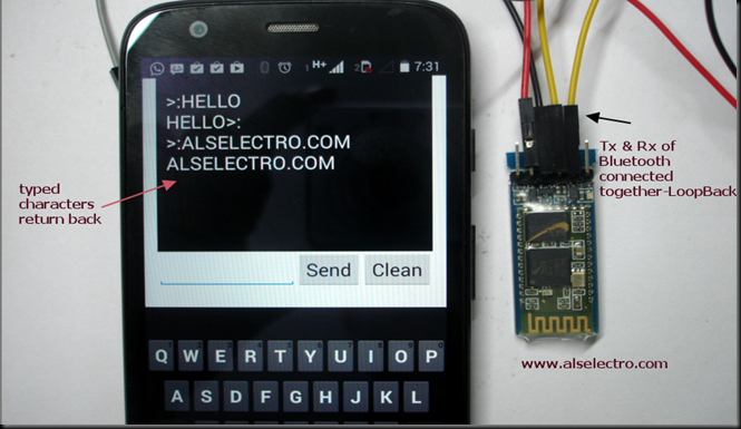
You can also test a Loopback method.
Connect the Tx & Rx of Bluetooth module together .For this test PC 7 USB board are not required.Justyou need to provide 5v power to module & loop the Tx/Rx.
Now the characters sent will be received back.
Watch this support video :
BLUETOOTH MODULES


沒有留言:
張貼留言