源自於http://nootropicdesign.com/projectlab/2012/02/18/xbee-robotics-platform/
Wireless Robotics Platform with XBee Remote Control
Difficulty Level = 7 [What's this?]
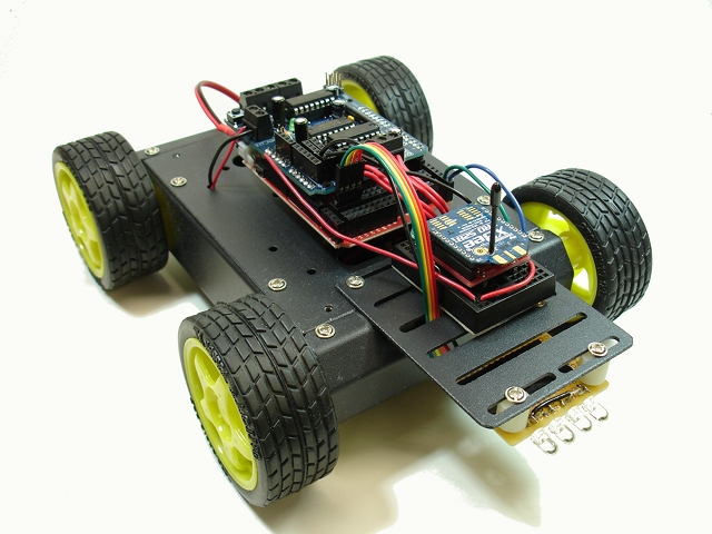
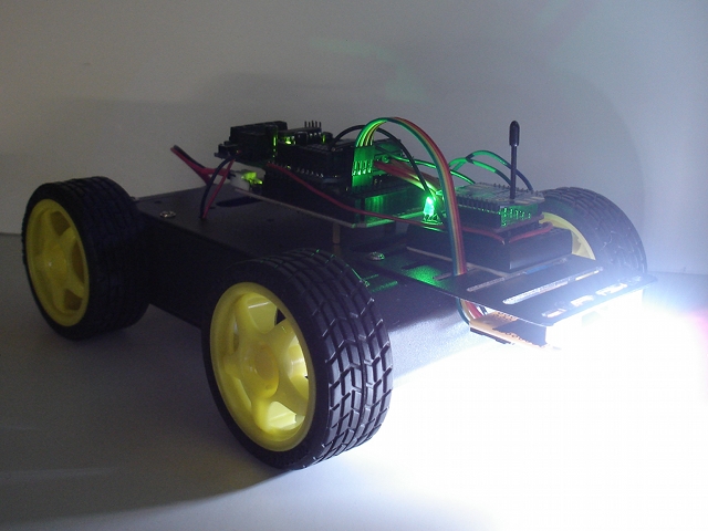
I built a remote-controlled robotics platform using a 4WD mobile platform, an Arduino (Seeeduino Mega), an Adafruit motor shield, and two XBee radios for communication. There are also some super-bright white LEDs on the front for headlights. The point of the project was to show how an XBee radio can be used to send joystick sensor data without using a microcontroller on the remote.
The vehicle is very easy to control using a joystick and a couple of buttons to control the lights. First I’ll describe how the remote control unit works, then I’ll show how the vehicle was built.
The Remote
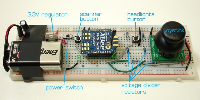
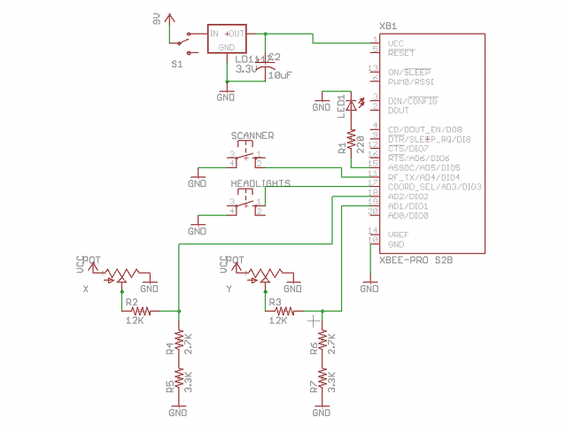
Here’s a picture of the remote control unit that I built on a breadboard. A Parallax joystick is used to control the vehicle, one button turns the headlights on/off, and another button puts the headlights in “scanner” mode, you know, like Kitt or like a cylon. The radio requires a 3.3V supply, but the analog pins cannot take more than 1.2V, so I used some precision resistors to form a voltage divider so that the analog input voltage was stepped down to less than 1.2V. Also note that the joystick is rotated 90 degrees so that it worked on a breadboard with this orientation.
To make this work, one radio needs to be running the “coordinator” firmware, and the other running the “router” firmware. In this project, the coordinator is on the vehicle and the router is on the remote control, but it should not really ma
I used the X-CTU tool from Digi to write the appropriate firmware to the radios and configure them. If you have not done this before, this is not a good project to start with. It is best to start with 2 radios that you already have working together using the API firmware.
The XBee on the remote control unit is configured to send analog/digital sample packets every 100ms. Pins AD1 (pin 19) and AD2 (pin 18) are configured as analog inputs and are connected to the potentiometers in the joystick. Pins DIO3 (pin 17) and DIO4 (pin 11) are configured as digital inputs for the two buttons on the remote that control the lights on the vehicle. Here is a list of the configuration parameters that were set on the remote radio:
The Vehicle
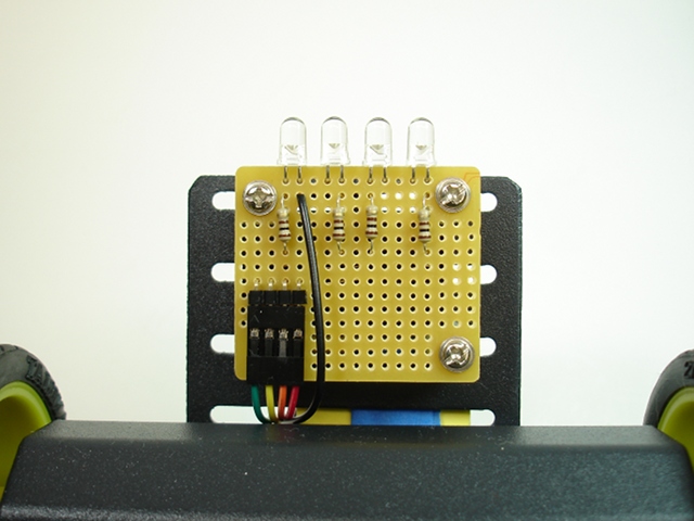
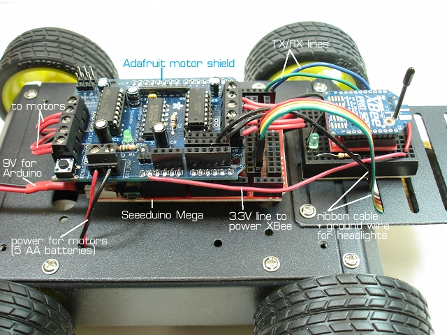
The wiring for the vehicle is fairly simple. Inside the 4WD platform are 5 AA batteries for powering the motors, and a 9V battery for the Arduino. I’m using a Seeeduino Mega because that’s what I had handy but any Arduino will work. The Adafruit motor shield is connected to the 4 DC motors inside the chassis. I used the 3.3V power supply on hte Arduino to power the XBee radio. The TX/RX lines of the radio are connected to the RX/TX pins on the Arduino. There’s a ribbon cable connecting 4 output pins to the LED headlights, and a ground wire running to the headlight assembly. Here is the bottom of the headlight assembly. These are 100 ohm resistors to keep the current draw below 20mA per LED.
 The Software
This code depends on the Adafruit library for using the motor shield, so download that and install it as an Arduino library. The Arduino sketch for this vehicle RobotVehicle.zip can be downloaded from here. Read the code for an explanation of how it works. The basic idea is to decode the incoming XBee API packets and map the joystick position information to the motor speeds. If the joystick is forward, all four wheels move forward. If the joystick is turned slightly to one corner, then the vehicle will move along an arc. If the joystick is hard left or right, then the wheels on the left side and right side will turn in opposite directions, causing the vehicle to rotate in place. By studying the code carefully, you should be able to understand how all of it works. Enjoy!
 |


沒有留言:
張貼留言