源自於http://www.azega.com/arduino-servo-motor-part-1/
Arduino Servo Motor
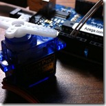
 Controlling a servo motor with an Arduino or other type of microcontroller is probably the easiest way to get started in robotics, motion art, or any other reason you may have to make your electronic project interact with the real world. Servos are very simple to interact with and in this post I’ll show you how to connect one to an Arduino.
Servo motors are a specific type of motor, often used in hobby RC cars and planes, that rotate to a specific angle when a corresponding signal is applied to the pulse pin. Servo motors are very easy to program and very strong for their size. This makes them useful for a wide array of applications. The internal components of a servo motor consist of a regular DC motor, which does the actual work, a system of gears to increase the torque to the output shaft, and a circuit board and sensors to control the movement of the motor.
Wiring:
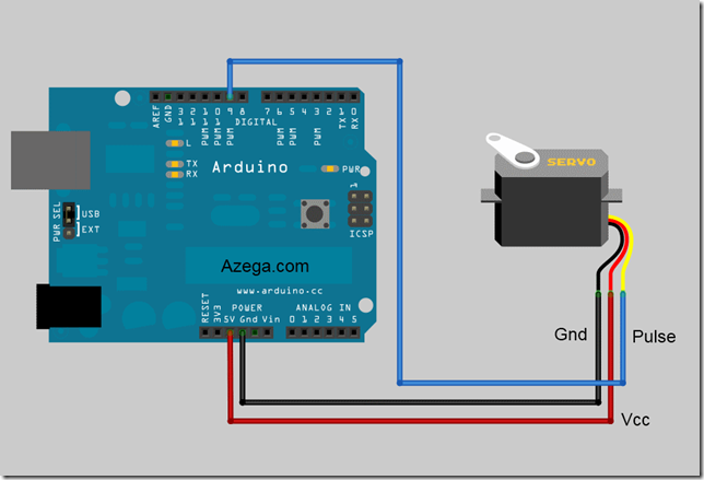
To get started controlling a servo with your Arduino, you only need to connect three pins. There are two pins for power and ground. For a small servo or just for testing, you can connect these directly to the Arduino. If you are controlling a large servo motor, you might want to use an external power source. Just remember to connect the ground from the external source to the ground of the Arduino.
The third pin is the pulse, or signal pin. This accepts the signal from your controller that tells it what angle to turn to. The control signal is fairly simple compared to that of a stepper motor. It is just a pulse of varying lengths. The length of the pulse corresponds to the angle the motor turns to. Typically a pulse of 1.25 milliseconds causes the motor to rotate to 0 degrees and a pulse of1.75 milliseconds turns it 180 degrees. Any length of pulse in between will rotate the servo shaft to its corresponding angle.Some servos will turn more or less than 180 degrees, so you may need to experiment.
Programming:
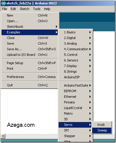
The Arduino software comes with a sample servo sketch and servo library that will get you up and running quickly. Simply load it from the menu as shown below. Their example uses pin 9 for the pulse wire, so to keep it simple, that’s what I used. You could use any of the data pins and, if you add more than one servo, you will need to. The Sweep sample simply rotates the servo back and forth from 0 degrees to 180. There is another sample sketch that uses a potentiometer as an input to control the angle of the motor, but I’ll get in to that later.
The code is pretty basic and well documented. It first loads the library needed and sets up which pin to use as the output.
This line tells it to move from 0 degrees to 180 degrees one degree at a time:
for(pos = 0; pos < 180; pos += 1)
And this line tells it to move back to 0 degrees one degree at a time.
for(pos = 180; pos>=1; pos-=1)
You can play around with those lines to get different effects. That is what I’ve done in the video below.


沒有留言:
張貼留言