Switching Things On And Off With An Arduino
One of the first projects many people new to the Arduino do is blinking an LED and there many many guides on line. Unfortunately, many of the guides never go beyond the very basic first sketch. In this guide, I hope to help new users take the next step.
Besides the obvious fact that blinking an LED is cool in its own right it is a good exercise because switching an LED on and off is the same process for switching any digital device on and off. Once you can create the code to blink an LED you can create code to turn anything on and off. Of course, you do not need to control an LED, you can use the same methods to do almost anything that is controlled in the same way. For example, I use similar techniques when setting up remote controls using Bluetooth and wifi connections and instead of setting a pin state I send control codes.
Polling vs interrupts
Connecting Arduino pins directly to vcc
Polling. Example 01: Very simply press for on, release for off
Polling. Example 02: Press for on, release for off. Slightly refined
Polling. Example 03: Toggle switch
Polling. Example 04: Multiple states from a single push button switch
Polling. Example 05: Start and stop an action
Part-2-Interrupt-Techniques
Interrupt. Example 01: Turning an LED on and off
Interrupt. Example 02: Turning an LED on and off with debounce
Downloads
Polling vs interrupts
There are many solutions to turning an LED on and off and a lot depends on how you want your sketch to work, how quickly you need the Arduino to react and what interface you want to use; one button switch, two button switches, a key pad, etc. Here I cover some of the ways I do it using a single button switch. I cover how to do this with polling and interrupts. The first section uses polling and in a future second section I will cover using interrupts.
Polling is where we are always checking the status of something. In the below examples, inside the loop() function we continuously check the pin state with digitalRead(). We do not know if the pin state has changed until we look at it. Polling is like checking the front door every minute or so to see if the postman is delivering your new Arduino.
Interrupts, as the name may suggest, is where the current process is interrupted and a new process is performed. In context of this post, the Arduino reacts to a pin state whether or not we are checking it or not. This means the code does not need to worry about the pin until the Arduino tells us to. This is like watching a DVD and the door bell rings. You stop the DVD and go check who is at the door. You sign for your new Arduino and go back to watching the DVD. Because you have a doorbell, you do not need to keep checking the door. You simply react when you hear it ring.
Please note: in all examples I am using 5V ATmega based Arduinos (specifically Arduino Nanos). If you are using 3.3v or non ATmega Arduinos you may (or may not) need to make adjustments. I do not cover these at this time.
Connecting Arduino pins directly to vcc
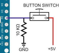
In the examples below I have the switch pin connected to a 10K resister, to GND and to the button switch. This means the pin is being pulled LOW. The other side of the switch is connected to vcc (in this case +5V) so when the switch is closed, the vcc over powers the 10K resister and connects the switch pin to 5V making it HIGH. Normally connecting an Arduino pin directly to 5V can be a bad idea but we can do it here because Arduino digital pins that are set for INPUT with pinMode have a very high impedance similar to having a 100 megohm resistor in front of the pin. This means we can safely connect the pin directly to 5V. For more information about this see www.arduino.cc/en/Tutorial/DigitalPins
This connection configuration is very hobbyist and you could create a similar circuit without the 10k resistor by using the Arduinos internal PULLUP resistor. This reverses the switch pin state, HIGH when open, LOW when closed though. I leave this for you to research and implement and a good place to start is Digital Pins on the Arduino website
Part 2: Polling Techniques
This first section has examples that use typical polling techniques. This is where the state of a pin is constantly checked and the code then decides what to do based on the pin value.
Polling. Example 01: Very simply press for on, release for off
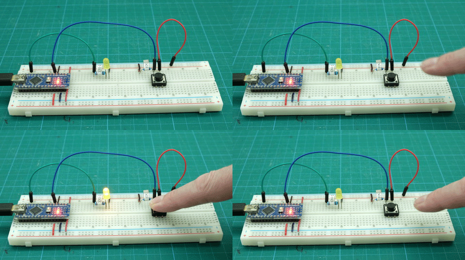
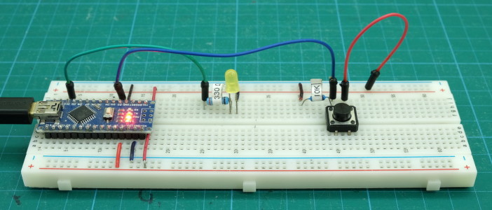
The first example keeps things as simple as they can be. We have a button switch and an LED. When the button switch is pressed the LED comes on. When the button switch is released the LED goes off.
Sketch: SwitchingThings_01
The code
When addressing Arduino pins you can simply use the relevant number, for example 2,3, 4 etc. This works fine but can lead to readability issues in the code, especially in large sketches or code that takes a while to develop. You may think it is perfectly clear that pin 10 is the LED but at some point you are likely to forget. To make code readable (or easier to follow) I find it better to use variables with meaningful names instead of the pin numbers. In this example; pin_LED and pin_switch. At the start of the sketch 2 variables used for the pins are defined and set. From the variable names it should be obvious what the pins are used for.
When addressing Arduino pins you can simply use the relevant number, for example 2,3, 4 etc. This works fine but can lead to readability issues in the code, especially in large sketches or code that takes a while to develop. You may think it is perfectly clear that pin 10 is the LED but at some point you are likely to forget. To make code readable (or easier to follow) I find it better to use variables with meaningful names instead of the pin numbers. In this example; pin_LED and pin_switch. At the start of the sketch 2 variables used for the pins are defined and set. From the variable names it should be obvious what the pins are used for.
The next step is to tell the Arduino how we want to use the pins. The pins can be used for inputs or outputs (or both if you know what you are doing). The LED pin is set to OUTPUT and the switch pin is set to INPUT.
If you connect an LED and forget to set the pin to OUTPUT it will not work correctly. The pin will still switch but it will not have the full voltage on it and the LED will light very dimly.
I also set the LED pin to LOW. This is habit I picked up many years ago and it is not really needed on the Arduino but it makes me feel better.
The sketch is fairly simply. Inside the loop() function the state of the switch pin is checked
and if the pin is HIGH the LED is turned on by setting the LED pin HIGH.
If the switch pin is not HIGH (IE LOW) the LED is turned off with
You should be able to see that the sketch is constantly checking the switch and turning the LED on or off accordingly. This means not only is the switch pin being constantly checked but the LED is constantly being turned on and off. For this short simply sketch this is fine and works well but may run in to issues when used in larger more complex sketches.
Although we cannot get away from continuously checking the button switch pin (this is what polling is) we can stop setting the LED pin every time and only set it if the state of the button switch has changed.
Polling. Example 02: Press for on, release for off. Slightly refined
Here we add a couple of switch status variables; one for the new state and one for the old state. We then compare them to see if there has been a change, and, if there has been, either turn the LED on or turn it off. This means we are not wasting time setting the LED pin when we do not need to.
We are using exactly the same circuit as above.
Sketch: SwitchingThings_02
This sketch appears to do exactly the same as the first sketch. Press the button switch and the LED comes on. Release the switch and the LED goes out. The difference is that we now only change the LED pin when the switch state has changed.
Two new variables have been added; oldSwitchState and newSwitchState.
The state of the switch is read and the value placed in newSwitchState. This is then compared to oldSwitchState. If they are the same we know no change has taken place and we do not need to do anything. But if they are not the same, then we know the switch has changed and we need turn the LED either on or off.
“!=” is NOT equal and is the same as “<>”
To determine if the LED needs to be turned on or off we are still using the switch state but now the state is stored in the newSwitchState variable.
Of course, if all you want is an LED to come on when you press a button switch you do not need an Arduino, simply wire the LED and switch in series and connect to power. Closing the button switch will complete the circuit and the LED will come. Release the switch and the LED turns off.
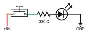
This does exactly the same as the above 2 examples without the Arduino.
Polling. Example 03: Toggle switch
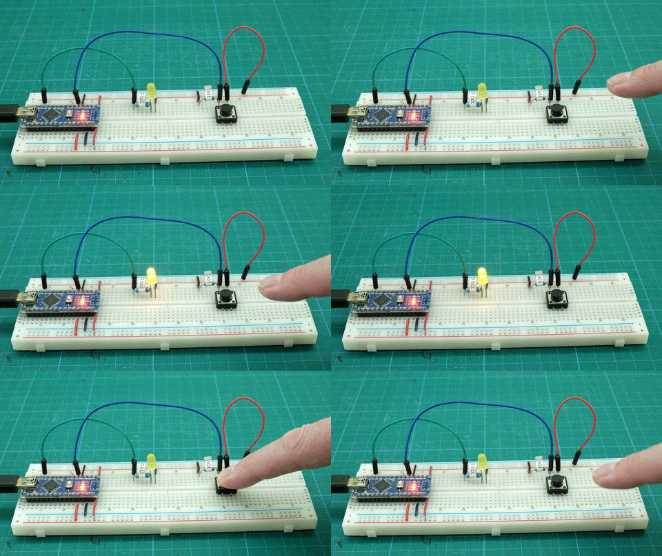
What if we do not want to hold the button switched closed to keep the LED on. What if we want to press once to turn on the LED and press again to turn it off. To do this we need to know when the button switch is pressed but was not pressed before (we have already done this in the previous example) and we also need to know the status of the LED; is it on or is it off? We can keep track of the LED status by adding a new variable LEDstatus. LEDstatus will be LOW for off and HIGH for on.
We are using exactly the same circuit as example 1 above.
Sketch: SwitchingThings_03: Toggle function
You may notice that the value of LEDstatus is the same as the value assigned to the LED pin. This means we could use it to set the pin and do away with one of the digitalWrite() statements.
Upload the sketch and give it a go. It works, sort of… You will probably notice that the LED turns on and off but not reliably. Sometimes, when you try to turn on the LED it will turn off straight away, and, when you try to turn it off, it will turn back on straight away. This is due to what they call bounce or switch bounce.
Switch bounce
With many kinds of switches, you do not get a clean closed contact, you get a very short transition period where the switch very quickly closes, opens, closes, opens and closes before settling down and becoming fully closed. The contacts bounce a bit before becoming fully closed. Hence the name switch bounce.
There are many solutions, both hardware and software, called debouncing. Some fairly simple, some more complex. For simple push button switches where super fast speed is not critical I generally use a very simple technique of sampling the pin several times and if all results are the same I can be confident I have a clean reading. Adding a short delay also helps.
I changed newSwitchState to newSwitchState1 and added newSwitchState2 and newSwitchState3.
This is not an original solution. I saw it somewhere on the internet a while ago and found it work very well. Unfortunately, I cannot remember where I first saw it.
Sketch: SwitchingThings_03a: Toggle function with simple debounce
Upload the new sketch and try again. This time you should get much cleaner and reliable on and offs.
Polling. Example 04: Multiple states from a single push button switch
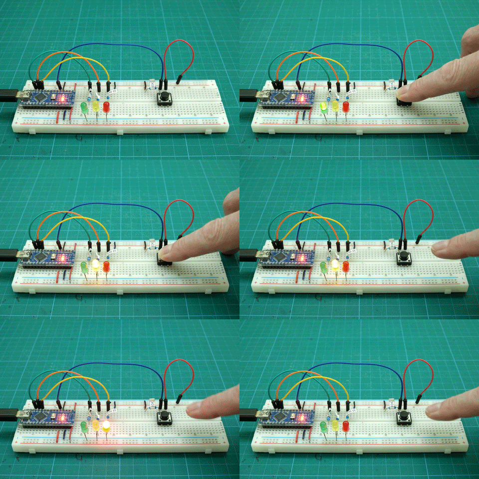
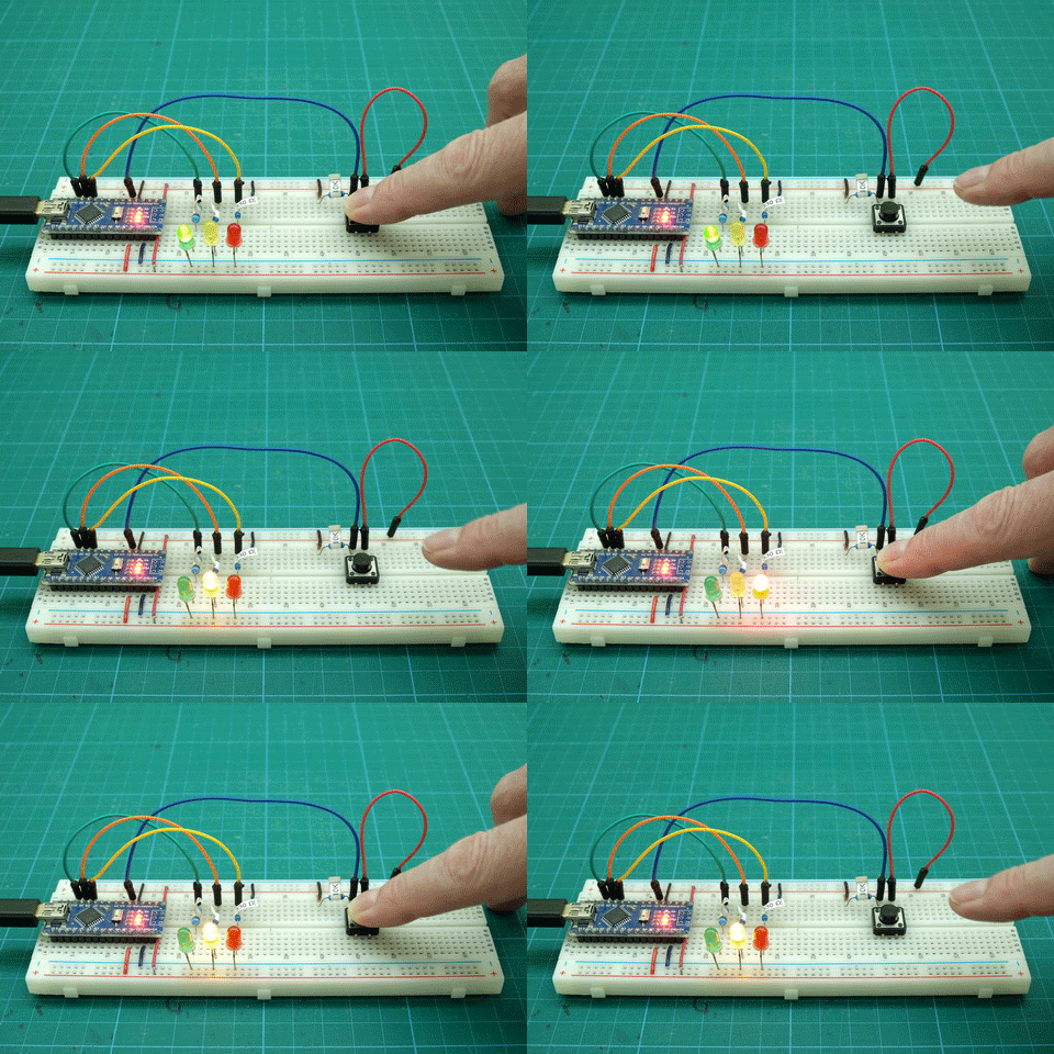
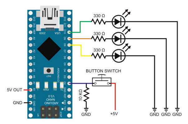
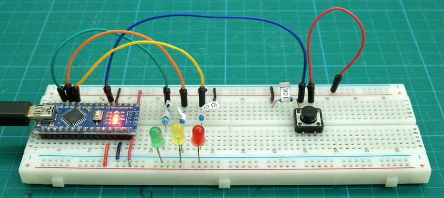
Here we control 3 LEDs with a single button switch. I have added 2 new LEDs to pins 9 and 8. Every time the switch is closed the next LED lights up. On the 4th press the LEDs reset to all off. To keep track of which LED is active I have added a new variable called state.
Since we now have 3 LEDS we need to define the 3 pins being used
and these are then initialised and set LOW in the setup() function.
To keep track of where we are, a new variable called state is used. state is a byte that can have 1 of 4 values (0 to 3):
– state = 0 – all LEDs off
– state = 1 – green LED on
– state = 2 – yellow LED on
– state = 3 – red LED on
– state = 0 – all LEDs off
– state = 1 – green LED on
– state = 2 – yellow LED on
– state = 3 – red LED on
Every time the button switch is pressed the value of state is increased by 1. When state is greater than 3 then it is reset to 0.
“state++” is exactly the same as “state = state + 1″
I have kept the logic as simple as possible and the LEDs are controlled with a series of if statements. Since state can only have 1 value at a time and the value does not change within the IFs I do not need to use else if, a simple list of basic if statements is all that is required. You could also use a switch/case statement.
There are different ways to do this but as always I like to keep it simple and straight forward and I believe when learning it is important to understand what is happening so that you can get things working as quickly as possible. If the code is unnecessarily complex you may be able to copy and paste it but you won’t understand it and so you won’t be able to adapt it to your own needs.
If I were using more LEDs I would put the pin values in an array and then use the state variable as the array index. See example 4a below.
Sketch: SwitchingThings_04: Multiple states from a single button switch
You may notice that there is no “if (state==0)” statement. To change which LED is on we first need to turn off the current LED. You may be tempted to put digitalWrite(pin, LOW) statements is all the “if” statements but this is not required. Since we know that we need to turn a LED off every time we can simply turn them all off (setting a pin LOW that is already LOW has no effect and will not hurt the Arduino) and then turn on the new LED.
Polling. Example 04a: Multiple states from a single push button switch refined

I mentioned in the previous example that if I were using more LEDs I would use an array to hold the pin numbers. Arrays allow you do to more than just hold the pin numbers though. An array can also be used to hold the on/off sequence. Here I use an array to hold the sequence; green, yellow, red, yellow, green, etc. With arrays this is fairly easy. Without them it can become complex.
The circuit is exactly the same as used in Example 4.
I have introduced 2 arrays. One for the pin numbers and one for the LED sequence. I also added a variable to store the sequence length. Although not really required in this simple sketch, using squenceLength means we can quickly change the sequence without changing the main code. All we need to do is update squenceLength to match the new array length.
Now we have an array for the pin numbers, we can use it when initializing the pins.
In the loop() function, now that we have a variable storing the length of the LED sequence array we use it to reset the state variable. remember that arrays in C start at position 0 so we need to reduce the squenceLength value by 1.
We then use the LED sequence array with the state variable as the index value to turn on the next LED.
“LED_Sequence_array[]” holds the pin number to use.
Sketch: SwitchingThings_04a: Multiple states from a single button switch, refined
Something to try. Now that we are using arrays, try putting the newSwitchState variables in to an array rather than using 3 separate variables.
Polling. Example 05: Start and stop an action
Using the same method as above we can start or stop any task or function. Instead of turning an LED on or off we can start and stop a motor, a sensor, or blink an LED. Not just turn it on and off with the button switch but to turn on a blinking LED. When the button switch is pressed the LED starts to blink. When it is pressed again the LED stops blinking. The following uses the blinking without delay technique.
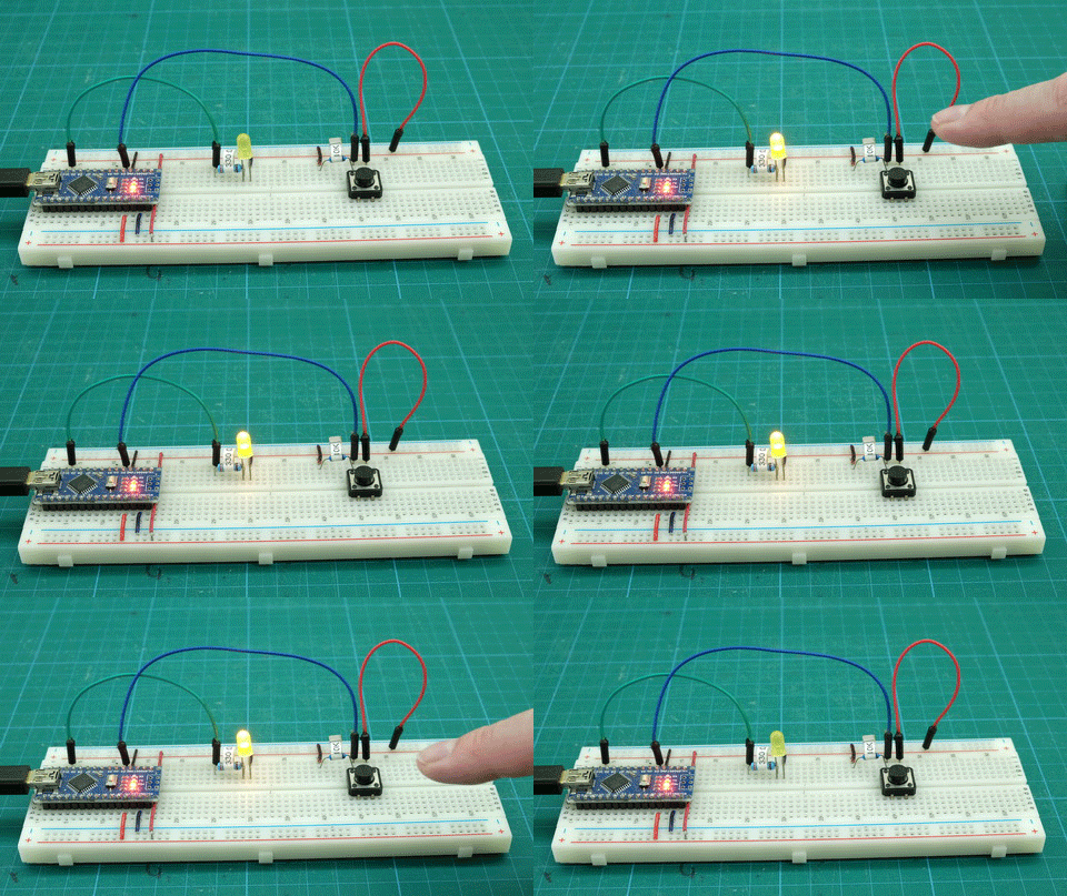
In this example I add slightly more advanced elements from the blink without delay technique that allows me to do 2 things a once.
Sketch: SwitchingThings_05: Using a button switch to turn on and off a blinking LED
This sketch is a little more complex than the previous ones but should be fairly straight forward to understand.
When the switch is pressed, instead of turning an LED on or off the variable keyPressed is set to true.
The value of keyPressed is then checked. If it is true the value of the variable flashingLEDisON is reversed; either true to false, or false to true. flashingLEDisON is used to tell the sketch if it should be blinking the LED or not.
To blink the LED we need a timer, this is used in the third section. This section checks to see:
1 – are we blinking the LED (is flashingLEDisON == true),
2 – and if so, is it time to turn the LED on or off
1 – are we blinking the LED (is flashingLEDisON == true),
2 – and if so, is it time to turn the LED on or off
To blink the LED I have used a very standard technique refereed to as “blink without delay“. The “blink without delay” allows you to do several things at once. This can be almost anything not just blinking an LED. In this example it allows me to blink the LED while still constantly checking for key presses.
There are a few new variables.
These act as flags to show if the button switch as been pressed, if the LED is blinking or not, and if the LED is on or off. I added a variable to record the key presses so that the code can start to be modular. This will then allow me to easily add functions and to further separate the code. The next example expands this.
Basically:
When the key is pressed KeyPressed is set to true.
If keyPressed == true the variable flashingLEDisON is set to true or false. When it is true we know to blink the LED.
LEDstatus lets us know if the LED is on or off.
When the key is pressed KeyPressed is set to true.
If keyPressed == true the variable flashingLEDisON is set to true or false. When it is true we know to blink the LED.
LEDstatus lets us know if the LED is on or off.
In the loop() function, the first part of the code checks the button switch and if it has been pressed (goes from LOW to HIGH) sets keyPressed to true.
The next section checks keyPressed, and if it is true, knows we are, either starting the blinking LED or stopping it. Again, this part is self contained and simply flips the value of the flashingLEDisON variable.
When the blinking LED is stopped, the LED may be on so, just in case, it is turned off. If you wished you could check LEDstatus first and only turn of the LED if it is actually on. At the end, keyPRESSED is reset to false ready for next time.
The final section actually blinks the LED. New variables have been introduced to hold the times and the rate of blink (timeWait). This is straight from the blink without delay example. We store the previous time, then get the current time. If the difference between the current time and the previous time is equal or greater than the blink rate we flip LEDstatus and then display the new LEDstatus. Basically, if we have waited the correct amount of time we either turn the LED on or turn it off to make it blink.
Although the code is longer, by doing it in distinct sections it is easier to understand and also it is easier to move to separate functions. Using functions will help make the code cleaner and clearer. It also means it is easier to adapt, all we would need do is change one of the functions.
Polling. Example 05a: Start and stop an action with added functions
This sketch does exactly the same as the one above. The only difference is that I have introduced functions; one that checks if the button switch has been pressed, one to start and stop blinking the LED, and a third that blinks the LED.
This means the loop() function is a lot shorter:
I also moved the newSwitchState1/2/3 initializations in to the function. These then become local variables.
This is just one of many different solutions to the same problem.
Part 2: Interrupt Techniques
Disclaimer: Being an oldskool programmer (I learnt programming many years ago on mainframes) I don’t use interrupts that often. I prefer to find alternative solutions using linear techniques if I can.
Using interrupts to check a button switch, in my opinion, is overkill but it can be a good technique to use when it is important to know or do something as soon as a switch is pressed or a pin changes state (rotary encoders come to mind). Unlike normal Arduino code which is linear and follows the instructions one after the other as you have written them, interrupts can happen at any time and will happen when the Arduino is in the middle of doing something else. Using interrupts can become complex and tricky quite quickly but if you have ever done any event driven programming the techniques are similar. I do not cover interrupts in any great detail. Just enough to get you started turning things on and off.
There are different kinds in interrupt and since this post is about switching things on and off with a button switch, we are going to use pin change interrupts. I do not cover other types of interrupt in this post.
Pin change interrupts
As the name implies, pin change interrupts happen when the state of a pin changes. There are 4 options:
LOW – the interrupt is triggered whenever the pin is LOW
CHANGE – the interrupt is triggered whenever the pin state changes
RISING – the interrupt is triggered whenever the pin state goes from LOW to HIGH
FALLING – the interrupt is triggered whenever the pin state goes from HIGH to LOW
LOW – the interrupt is triggered whenever the pin is LOW
CHANGE – the interrupt is triggered whenever the pin state changes
RISING – the interrupt is triggered whenever the pin state goes from LOW to HIGH
FALLING – the interrupt is triggered whenever the pin state goes from HIGH to LOW
In these examples I will be using RISING. This is the same as the polling examples; when the button switch is closed, the pin goes from LOW to HIGH (it rises).
When using interrupts on the Arduino;
1 – you need a function that contains the code to execute.
2 – you need to tell the Arduino to use this function when the interrupt occurs, and
3 – you need to tell the Arduino what type of interrupt to use.
1 – you need a function that contains the code to execute.
2 – you need to tell the Arduino to use this function when the interrupt occurs, and
3 – you need to tell the Arduino what type of interrupt to use.
The interrupt function or Interrupt Service Routine (ISR) is like but not exactly the same as other Arduino functions. ISRs cannot accept arguments and they cannot return values. This means if you need to pass values you need to use global variables (this needs some special consideration though). There are certain things that do not work and there are certain things you shouldn’t really do inside the ISR. Delay() should not be used (it uses interrupts so doesn’t work inside an ISR), millis() will not work and serial print doesn’t work correctly.
As a general guide; ISRs should be as short as possible and not do anything overly complex.
The attachInterrupt() command
To tell the Arduino to use interrupts you use the attachInterrupt() command. attachInterrupt() has 3 parameters; attachInterrupt(param1, param2, param3)
param1 – the pin to use
param2 – the function or ISR to call when the interrupt is triggered
param3 – the mode or type of interrupt to use
param1 – the pin to use
param2 – the function or ISR to call when the interrupt is triggered
param3 – the mode or type of interrupt to use
Pin to use
Different Arduinos can use different pins for interrupts. ATmega 328 based Arduinos like the Nano can use pins 2 and 3 only. The Mega can use pins 2, 3, 18, 19, 20, and 21.
| Board | Available digital pins |
| 328-based (Nano, Mini, Uno) | 2, 3 |
| Mega | 2, 3, 18, 19, 20, 21 |
| 32u4-based (Micro, Leonardo) | 0, 1, 2, 3, 7 |
| Zero | all digital pins except pin 4 |
| Due | all digital pins |
| 101 | all digital pins Only pins 2, 5, 7, 8, 10, 11, 12, 13 work with CHANGE |
param1: interrupt number
On ATmega328 based Arduinos there are 2 interrupts INT0 and INT1, these point to or are mapped to pins d2 and D3, and normally you address them by using the values 0 and 1. So for param1, we would use 0 for pin D2 and 1 for pin D3. This is fine if you are only every going to use an ATmega 328 based Arduino, INT0 will always be D2 and INT1 will always be D3. The problem is, on other types of Arduino, INT0 is not always D2 and INT1 is not always D2. To get around this the Arduino developers introduced the system variable digitalPinToInterrupt(pin) and on the Nano, digitalPinToInterrupt(2) = 0 and digitalPinToInterrupt(3) = 1. This means, when we use a variable for the pin number, such as pin_switch, we can use digitalPinToInterrupt(pin_switch) and not worry about the exact interrupt number. Nor do we need to worrt about converting the code to work on other types of Arduinos.
param2: ISR
param2 is simply the name (without the brackets) of the function that should be called when the interrupt is triggered. So if you have a function called blink(), you simply use “blink”.
param3: interrupt type
As mentioned above, there are 4 types of interrupt and you specify which one you want to use by using one of 4 system variables; LOW, CHANGE, RISING, or, FALLING. Since the trigger is the push button switch being pressed and the pin status going from LOW to HIGH we are using RISING.
The full command is:
attachInterrupt( digitalPinToInterrupt(pin_switch), blink, RISING )
This is then placed in the setup() function.
Of course, we also need a function called blink:
void blink()
{
    if (LEDstatus == HIGH) { LEDstatus = LOW; } else { LEDstatus = HIGH; }
    digitalWrite(pin_switch, LEDstatus);
}
I am using an ATmega 328P based Arduino that can use pin change interrupts on pin D2 and D3 only. Luckily (or was it planned…) I already have the button switch connected to D2 so I can use the same circuits as above.
Interrupt. Example 01: Turning an LED on and off
Here we do the same as example 3 above. When the button switch is closed we turn the LED either on or off. The difference here is that we are using an interrupt to monitor the switch pin.
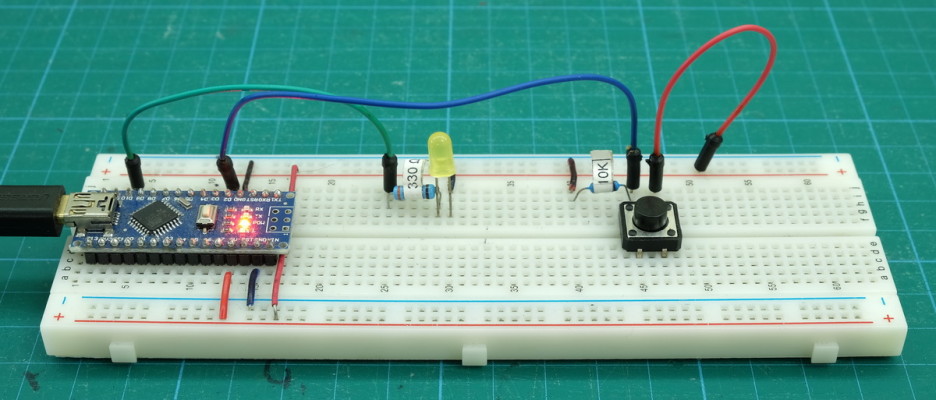
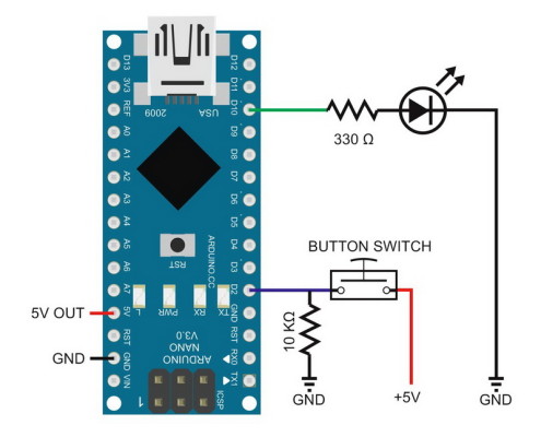
Sketch: Interrupt example 01: Turning an LED on and off
When the button switch is pressed the interrupt is triggered which calls the blink() function. The blink() function flips the value of LEDstatus and then updates the LED.
You will notice is that the loop() function is empty. Since the interrupt is watching the switch pin and then calling the blink function directly, code in the loop() is not required.
You may also notice that there is no debounce and we are back to having unreliable key presses. When using interrupts it is not so easy to debounce the key switch in software but we can give it a go.
Interrupt. Example 02: Turning an LED on and off with debounce
Here we do the same as above, use an interrupt to detect a key press and then turn an LED on or off. But unlike the example 1 where the interrupt called the routine to change the LED directly, this time, we use the interrupt to set a flag to let us know the key has been pressed. Using an ISR to change the value of a variable is not always reliable, sometimes the Arduino does not update it in time and when we get back to the main code the old value may still be used. To ensure the Arduino (actually the compiler) always uses the latest value we declare the variable as volatile. When a variable is declared as volatile the compiler will always use the latest value.
Sketch: Interrupt example 01: Turning an LED on and off
When the button switch is pressed the interrupt is triggered which calls the keyIsPressed() function. All the keyIsPressed() function does is set the variable keyPressed to equal true.
In the main loop() function, we check the value of keyPressed and if true we know the key has been pressed.
Because of switch bounce we may get key presses very quickly, to try and filter this the sketch checks how long since the last key press, and if the time is inside the debounce time the key press is ignored. For the button switch I am using about 10ms is required. This will be different for different switches. This is not a perfect solution though.
Final note. I would probably never use interrupts in this way, I included then in the guide to show that it is possible but I don’t like all the extra debouncing work you need to do to to ensure you have a clean trigger.


沒有留言:
張貼留言