Rain Gauge Mechanical Details
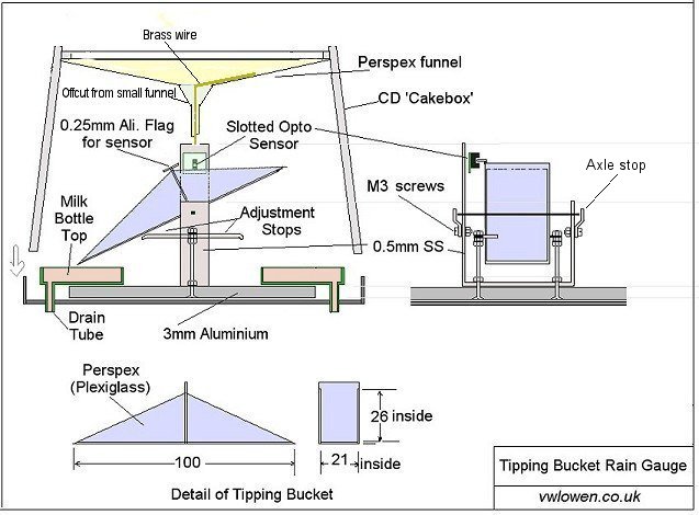
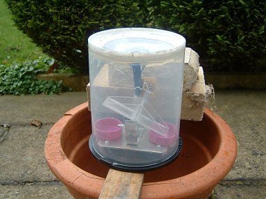 | As much as possible, I made the rain gauge from plastic and stainless steel, although the base plate is made from 3mm thick aluminium for rigidity. I'll need to keep an eye open for possible corrosion between the two metals.At the 'heart' of the rain gauge is a small "tipping bucket" arrangement made from Perspex (plexiglass) 1mm thick. Each bucket holds up to 6mL of water before its shifting centre of gravity causes it to tip discharging its water into the drainage 'container' - the plastic top from a milk bottle (Actually, the cat'smilk bottle!). As the bucket tips, an aluminium flag attached to the central divider passes through an optical sensor, sending a signal to the outdoor unit's electronics. I used an old 100-CD Cakebox for the outer casing. The sides of the box I used project about 7mm above the level of the top surface, forming a "wall" around the funnel opening. Hopefully, this will help prevent squally winds blowing the rain out of the funnel, although I suspect it will end up with a grill or grating of some sort fitted over the top. For the moment, I've left it with clear plastic (because it's interesting to watch it working!) but I suspect it'll need a coat of white paint to help reflect the heat once (if) our Summer arrives. |
[Update: 19th Sept 2013]Renewed the CD case as the old one had become brittle. See: blog.vwlowen.co.uk/?p=447
[Update: May 2017]Renewed the cover again.
[Update: May 2017]Renewed the cover again.
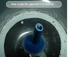 I couldn't find a funnel that was shallow enough to fit inside without the spout fouling the tipping bucket so I made one by cutting a disc of perspex and shaping it by placing it on an upturned glass saucepan lid in the kitchen oven to allow it to soften and sag into the lid. (Gas mark 3 for about 10 minutes!). A hole is drilled in the centre and a short piece of funnel is superglued on to form the spout.
Note the brass wire superglued inside the funnel and passing down the centre of the spout. This helps to stop surface tension holding the water in the funnel and helps the rain drip uniformly out of the spout. Without the wire, the rain had a tendency to "swirl" as it left the spout so its trajectory into the bucket was a bit unpredictable.
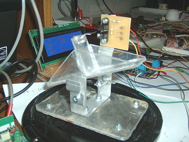 Tipping bucket rain gauge at the prototyping stage. Tipping bucket rain gauge at the prototyping stage. | 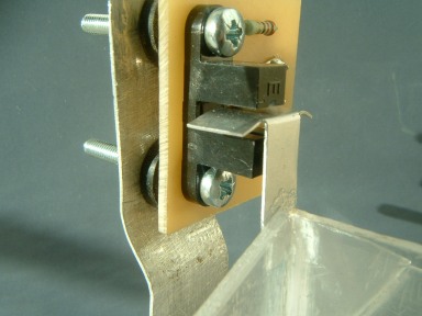 Close-up view of the aluminium flag and opto-sensor. Close-up view of the aluminium flag and opto-sensor. |
The printed circuit board will be fully water-proofed once everything is adjusted and working. The terminal block is mounted on the back of the board to keep it out of the way of the aluminium flag and to help keep it away from the rainwater.
Rain Gauge Electronics
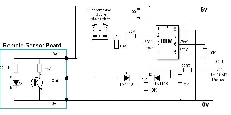 The 08M Picaxe and its associated circuitry is situated alongside the main 18M2 Picaxe on the Outdoor Unit's PCB.
Because of the random nature of the sensor's operation, a software interrupt in the Outdoor Unit's 18M2 Picaxe chip seemed the logical approach. Unfortunately, certain program commands, including serout and readtemp - both of which the program uses extensively - disable the interrupt mechanism while they are executing, meaning a high percentage of "bucket tips" were likely to be missed. Also, according to the Picaxe manual, although the count command doesn't disable interrupts, the timing of the count will be corrupted by interrupts and the program uses the count command to determine the wind speed.
For these reasons, the rain gauge has an 08M Picaxe to itself.
Using a separate chip with very little 'work' to do has the advantage of being able to use it to generate a reasonably accurate 1-hour time delay in order to count the bucket-tips per hour. Communicating that count to the main 18M2 Picaxe is reasonably straightforward and requires two of the 18M2 I/O pins. One issues a "request" in the form of an interrupt to the 08M which responds by sending the bucket-tip count using 'serout'.
As the 08M needs two interrupt inputs (one for the request from the 18M2 and one for the signal from the tipping-bucket sensor), they have to be 'Diode -ORed' because the 08M does not natively provide the OR function on its interrupts. (Thanks BeanieBots). Either input will, therefore, generate the interrupt on the pin designated by the setintcommand (Pin4) and the interrupt routine itself then polls to see which input was the actual culprit.
The use of 'serout' with active interrupts works ok here because the serout is actually under the interrupt's control. If the rain sensor were to be connected directly to the main 18M2 Picaxe, there would be a high probability that the interrupt would try to occur when it had been disabled during an active serout or readtemp command.
The main one-hour delay created in the 08M is the for w0 : next loop in the code shown below. The reason for not having the more usual 60 x 1 minute pauses is that the interrupt terminates the current pause. Here, the maximum terminated pause is 60ms and some of that will be regained because of the execution time of the interrupt routine itself. The timing isn't exact but it tends to average out over a few hours and it's close enough for this purpose bearing in mind the expected accuracy of the overall rain gauge.
For other circumstances, where timing may be more critical, there's a really elegant solution by Jeremy Leach to the problem of interrupts terminating a current pause command and is shown on the Picaxe forum. Unfortunately, the SetTimer command, which is used in the solution, isn't available on the 08M chip so we can't use it here.
The 08M Code
     #picaxe 08M

   Symbol ThisHour = b2    ; Store the current sensor count in b2
   Symbol LastHour = b3    ; Save the previous hour's count in b3

   ;Hardware definitions

   Symbol DataRequest = pin3
   Symbol BucketSensor = pin4


   setint 010000, 010000   ; pin4 is interrupt pin
      main:
          for w0 = 1 to 60000    ; Loop for 1 hour
             pause 60
          next
          LastHour = ThisHour    ; Update Last hour's count with
          ThisHour = 0     ; current hour & reset current hour

          goto main     ; Do the next hour

      interrupt:
          setint 010000, 010000   ; Re-instate interrupt

          if DataRequest = 1 then   ; Was the interrupt from the 18M2 ?
             serout 2, N2400, ("r", LastHour, ThisHour) ; Yes, so send previous hour's count & curent count.
             do : loop while DataRequest = 1  ; Wait until 18M2 stops requesting before continuing
          endif
          if BucketSensor = 1 then   ; Was the interrupt from the rain sensor?
             inc ThisHour    ; Yes, so increment bucket-tip count
             do : loop while BucketSensor = 1  ; Make sure flag has cleared sensor before continuing
          endif

          return
Rain Gauge Calibration
Once the main outdoor 18M2 Picaxe has received the current number of bucket-tips during this hour and the total number during the previous hour, it simply passes the numbers on to the indoor unit.
As a starting point, I'm using the following:
The funnel opening is 120mm diameter giving it a surface area of 11,311 mm2
1mm of rain will obviously be 11,311 mm3 or 11.3 mL.
Each bucket in the gauge is adjusted with the mechanical stops so that, ideally, it tips at 5.65 mL. Therefore, a count of 2 tips means 2 x 5.65 = 11.3 mL (or 1mm) of rain has fallen. One tip = 0.5mm of rain.
When I make my first trip this year to the garden centre, I'll pick up a cheap plastic rain measuring cylinder to check the calibration. There doesn't seem to be any room for manoeuvre in the maths so adjustment will be limited to the mechanical stops on the tipping bucket.


沒有留言:
張貼留言