Mosfet Driver Module IRF520
This little module is a breakout board for the IFR520 MOSFET transistor (Metal Oxide Semiconductor Field-effect Transistor), a module can adjust the output PWM. The module is designed to switch heavy DC loads from a single digital pin of your microcontroller. Its main purpose is to provide a low-cost way to drive a DC motor for robotics applications, but the module can be used to control most high current DC loads. Screw terminals are provided to interface to your load and external power source. A LED indicator provides a visual indication of when your load is being switched.
Applications
LED lights dimmer, variable speed for DC motors, miniature pumps, solenoid valves
Specifications
- Input Voltage: 3.3V ~ 5VDC
- Output load voltage: 0-24V
- Output load current: <5A (More than 1A required a heat sink)
- Weight: 10g
- Size: 33.5 x 25.5mm

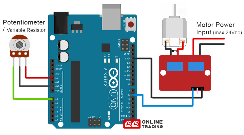
Connection to Arduino

Suggest to use a 100k / 10k variable resistor and a 1N4004 diode at the motor end.
#include "HCMotor.h" //Include HCMotor Code Library
#define MOTOR_PIN 6 // Assign to PWM/Digital Pin 6
#define POT_PIN A0 // Set analog pin at A0 for the potentiometer

HCMotor HCMotor; // Create an instance code library

void setup()
{

  HCMotor.Init(); //Initialise our library
  HCMotor.attach(0, DCMOTOR, MOTOR_PIN); // Attach our motor to 0 to digital pin 6
  HCMotor.DutyCycle(0, 100); //Set duty cycle of the PWM Pulse with Modulation signal in 100uS increment to 100uS = 1mS cycle
}

void loop()
{
  int Speed;
  Speed = map(analogRead(POT_PIN), 0, 1024, 0, 100); //Reading the A0 pin to determine the position of the pot.
  //mapping the motor which could be 0 - 1024 and reduce down to match the cyccle range of 0 to 100
  HCMotor.OnTime(0, Speed); // Set the duty cycle to match the position
}


沒有留言:
張貼留言