Band Pass Filter Calculator
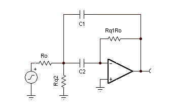
The filter topology here is actually a subset of the MFB topology. However, most programs and calculators for the MFB topology give no consideration of component value sensitivities - hence the need for this calculator. Equations were actually developed empirically from the Deliyannis bandpass topology, which I quickly realized could be converted to the MFB by the addition of a single resistor. By using this "modified Deliyannis" way of calculating the components, a filter can be easily designed that has low sensitivity to component value variations.

Notes:
- The gain and Q of the filter are linked together in this topology - a Q of 10 will also produce a gain of 10, etc.
- Practical limits are a Q of about 50 on the high end, and 1 on the low end.
- For values of Q less than 0.5, consider cascading a high pass filter and a low pass filter - the results will be better than you can get with this calculator
- The open loop gain of the op amp selected must be at least 40 dB greater than the gain of the op amp at the resonant frequency.
- The input impedance of the op amp becomes important as RQ1 increases in value, for large values of Q you may need an FET input type op amp. You can combat this by scaling the R's and C's, but remember you need to use an NPO type capacitor for stability.


沒有留言:
張貼留言