When I searched on “AM radio antenna design”, the best result I found was How to Make the Ultimate AM Antenna by R. Wagoner. The design looked right, but only by making one could I find out how good it was. The result is audibly better AM reception at my home in Mesa, Arizona.
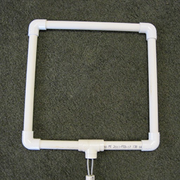
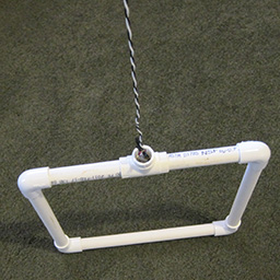
The original wooden frame was problematic to build (and alas, not very substantial) so I tried substituting plastic pipe for the wood, with the antenna wires on the inside. This proved to be durable and easy to construct.
Here are the parts ...
| |||||||||||||||||||||||||||||||||||
 | |||||||||||||||||||||||||||||||||||
Here’s how to assemble the antenna:
| |||||||||||||||||||||||||||||||||||
 You can turn the antenna in any direction to get the best AM radio reception. | |||||||||||||||||||||||||||||||||||
Ted,
This was fascinating and I have a few observations to share.
The verbal description was excellent, yet when I referred to the photographs there seemed to be disconnect when you said “Cut all but one of the wires on the left, and all but one of the wires on the right,” since when I referred to the photo I saw only one long wire. Turns out that the background color, the wire color, and my “first look” observation skills did not allow me to see the black wire. Fortunately I continued to follow the instructions to the end, then went back and read it again with the knowledge that there had to be two long wires, and walla there they were. Once the black wire is seen it is obvious in subsequent looks. Working in medical imaging, I am always fascinated by the way the human visual system filters image information, causing some things to be invisible until they are pointed out.
I am curious whether the shape and size of the loop is critical to the efficiency of the AM reception and how you determined the optimum design.
For those that don’t have any engineering or science background, it would help to show how the antenna is connected to the radio, perhaps even several different radios to demonstrate different means/locations of the connection.
You might also want to check out the broadcast Digital TV Antenna described in the attached document. You might also want to check out the broadcast Digital TV Antenna described in Makezine.
Loved your post. Thank you for sharing.
Phil RauchPhil,
Thanks! It’s great to hear from you.
The green carpet in my living room might not have been the best background. I’d thought about using a table, or the concrete floor on the patio, but wound up on my living room carpet.
The shape and size of the AM antenna are optimal, according to Wagoner. I don’t know enough about antenna design to say much more, so I adopted Carver’s design as given.

On the back of my stereo receiver (and apparently most) there are antenna jacks marked for AM and FM. For best reception you should use both an AM antenna and an FM antenna, just by inserting the wires in their corresponding jacks.
The Digital TV Coat Hanger Antenna looks interesting. We didn’t throw away all of our metal coat hangers when my family switched to plastic.
Ted |


| updated October 14, 2013 | Mile 204 | Ted Tenny |


沒有留言:
張貼留言