2021年3月22日 星期一

DE2-115 開發 以及閘AND Gate 為例(Verilog)

 DE2-115 開發 以及閘AND Gate 為例(Verilog)


//7408 AND Gate

module gate_7408_and( SW,LEDR );

input [17:0] SW;

output [17:0] LEDR;

and_gate(SW[17:0],LEDR[17:0]);

endmodule

//======================

//-- and_gate.v

//-- Component has an input (Din) and an output (Dout)


module and_gate( Din, Dout );

    input [17:0]Din;

    output [17:0]Dout;

    //-- Both the input and the output are "wires"

   wire [17:0]Din;

  wire [17:0]Dout;

      //-- Assign the nand of the input, to the output


    //gate-level modeling  

   and(Dout[0], Din[0], Din[1]);

   and (Dout[2], Din[2], Din[3]);

   // Data flow modeling

    assign Dout[4]= (Din[4] & Din[5]);

    assign Dout[6]= (Din[6] & Din[7]);

    assign Dout[8]= (Din[8] & Din[9]);

    assign Dout[10]= (Din[10] & Din[11]); 

   assign Dout[12]= (Din[12] & Din[13]); 

    assign Dout[14]= (Din[14] & Din[15]); 

    assign Dout[16]= (Din[16] & Din[17]); 

   //behavioral modeling

endmodule

DE2-115 開發 以反及閘NAND Gate 為例(Verilog)

 DE2-115 開發  以反及閘NAND Gate 為例(Verilog)

gate-level modeling  & Data flow modeling 

記得要import pin assignment [DE2_115_pin_assignments.csv] 


//7400 NAND Gate

module gate_7400_nand( SW,LEDR );

input [17:0] SW;

output [17:0] LEDR;

nand_gate(SW[17:0],LEDR[17:0]);

endmodule

//======================

//-- nand_gate.v

//-- Component has an input (Din) and an output (Dout)

module nand_gate( Din, Dout );

    input [17:0]Din;

    output [17:0]Dout;

    //-- Both the input and the output are "wires"

    wire [17:0]Din;

    wire [17:0]Dout;


      //-- Assign the nand of the input, to the output

    //gate-level modeling  

    wire Y;

    and(Y, Din[0], Din[1]);

    not(Dout[0], Y);

    nand (Dout[2], Din[2], Din[3]);

    // Data flow modeling

    assign Dout[4]= ~(Din[4] & Din[5]);

    assign Dout[6]= ~(Din[6] & Din[7]);

    assign Dout[8]= ~(Din[8] & Din[9]);

    assign Dout[10]= ~(Din[10] & Din[11]); 

    assign Dout[12]= ~(Din[12] & Din[13]); 

    assign Dout[14]= ~(Din[14] & Din[15]); 

    assign Dout[16]= ~(Din[16] & Din[17]); 

     //behavioral modeling

endmodule


DE2-115 開發步驟 以反相器為例

DE2-115 開發步驟 以反相器為例

參考來源 https://coldnew.github.io/4d1ad2ce/

本文將採用業界比較常用的 Verilog 進行示範,在參照這篇文章之前,需要自行安裝好 Intel® Quartus® II 9.1sp2 或是進階版本。

我們要透過純粹的可程式邏輯(Programmable Logic, PL) 去控制 LED,也就是說,我們只寫硬體描述語言 Verilog 來控制 DE2-115 上面的 LED,讓他依照我們設定的反相器功能進行亮滅。


建立專案

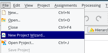
我們首先透過 File -> New Project Wizard 建立一個新的專案


進入點(top-level design entity) --> interver


DE2-115 配備 Cyclone IV E 系列晶片中最大容量的
Cyclone EP4CE115F29C7  FPGA,提供 114,480 邏輯單元 (LEs) 以及高達 3.9 Mbits RAM 與 266 multipliers。


撰寫程式

檔案除存為 inverter.v (注意到這個模組名稱和前面提到的 進入點(top-level design entity) 要相同)

//===================================

//Inverter

module inverter( SW,LEDR );

input [17:0] SW;

output [17:0] LEDR;

inv(SW[17:0],LEDR[17:0]);

endmodule


//======================
//-- inv.v
//-- Component has an input (Din) and an output (DoutB)
module inv(Din,Dout );
    input [17:0]Din;
    output [17:0]Dout;
    //-- Both the input and the output are "wires"
    wire [17:0]Din;
    wire [17:0]Dout;
    
      //-- Assign the inverse of the input, to the output
    assign Dout= ~Din;
    
endmodule

//===================================

腳位設定  (DE2_115_pin_assigment.csv) 匯入


DE2-115-pin-assigment 檔案下載位置
編譯
順利的話,Quartus 會提出我們程式的報告

下載(燒錄)到 DE2-115

要下載到 DE2-115 的話,選擇 Tools -> Programmer 召喚下載用的程式


假設在 Programmer 頁面下,並未看到 USB Blaster 這樣的下載器資訊的話,你可能需要點選一下 Hardware Setup 去指定下載器

結果
我們已經下載完成,去看看我們的板子的顯示狀況吧 !

將ter-asci DE2-115 板子上的SW[0]到SW[17] 切往上(1)或往下(0) 並觀察相對的紅色LED
LEDR[0]到LEDR[17]的亮滅是否符合 反相器功能進行亮滅。


Windows安裝USB-Blaster驅動程式

照理說到「裝置管理員」更新驅動時選擇USB-Blaster的驅動程式目錄(quartus\drivers\usb-blaster)即可安裝


但最近安裝USB-Blaster時Windows卻出現「此檔案可能已損毀」之類的訊息,Google搜尋一段時間之後終於找到解決方法
http://blog.csdn.net/chengbozhe/article/details/47335391
按照此網頁的 「問題二」即可解決


DE2-115 Verilog code for 4:1 Multiplexer (MUX)

 DE2-115 Verilog code for 4:1 Multiplexer (MUX)


//Mux 

module mux2_de2( SW,LEDR );

input [17:0] SW;

output [17:0] LEDR;

mux2(SW[17:16],SW[3:0],LEDR[0]);

endmodule


//======================

module mux2( select, d, q );

input[1:0] select;

input[3:0] d;

output q;

reg q;

wire[1:0] select;

wire[3:0] d;

always @(d or select)

q = d[select];

endmodule


DE2-115 Pin assigment

https://www.mediafire.com/file/1c3we0lftdz3qaq/DE2_115_pin_assignments.csv/file

Examples verilog.v

https://www.mediafire.com/file/kngm038siz036kj/ex1.rar/file


  清除項目編譯快取 執行 flutter clean 重新取得套件依賴 執行 flutter pub get 完整重新編譯並執行 flutter run 1. 新增專案套件 (pubspec.yaml) 在 Flutter 專案根目錄下的 pubspec.yaml 中,新增 ...