Node-Red with 3 ESP8266 DHT11 Sensor Modules
源自於 https://techblogs2017.wordpress.com/2017/07/01/node-red-with-3-esp-sensor-modules/
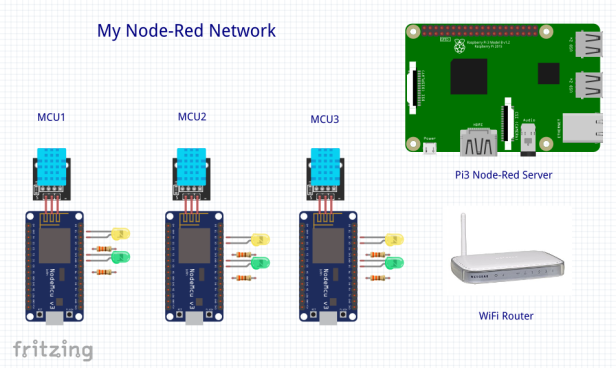
In my early experimentation with setting up a Node-Red system I had little trouble using sensors and servos with the Pi (which is the Node-Red server), nor communicating with a single ESP module to command it to turn on LEDs or read its sensors. However, I did encounter trouble when I added multiple ESP modules: when a second module was plugged in it bumped the first off of its connection to the server. After much struggling and searching I contacted the author of the Home Automation course mentioned in my first blog and discovered that I needed to create a greater separation of my groups, topics and ESP module ‘clients’ in both the ESP/Arduino code and also in my Node-Red server. This blog is my documentation of how I got 3 NodeMCU ESP8266 WiFi modules to work simultaneously in my home network with 2-way communication.
They key is a little bit of advance planning:
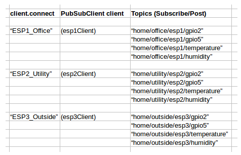
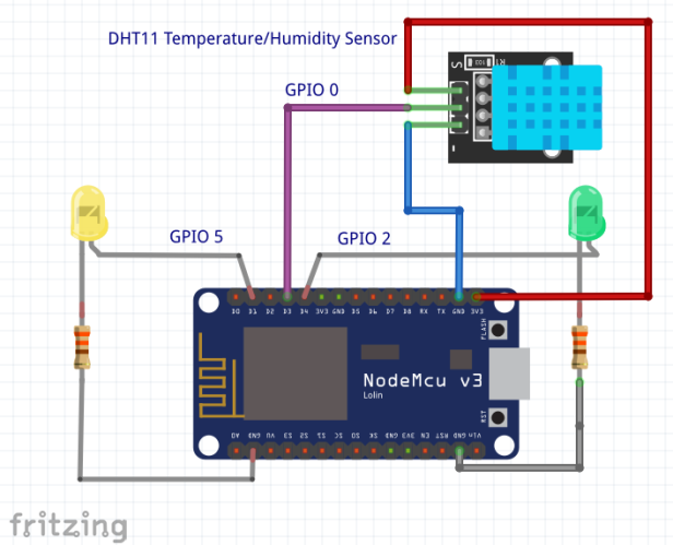
Just as the matrix would imply; I have a sensor module in my office, the utility room and outside on the patio. The GPIO topics 2 and 5 control LEDs on these NodeMCU modules and the topics of temperature and humidity come from the DHT11 sensor.
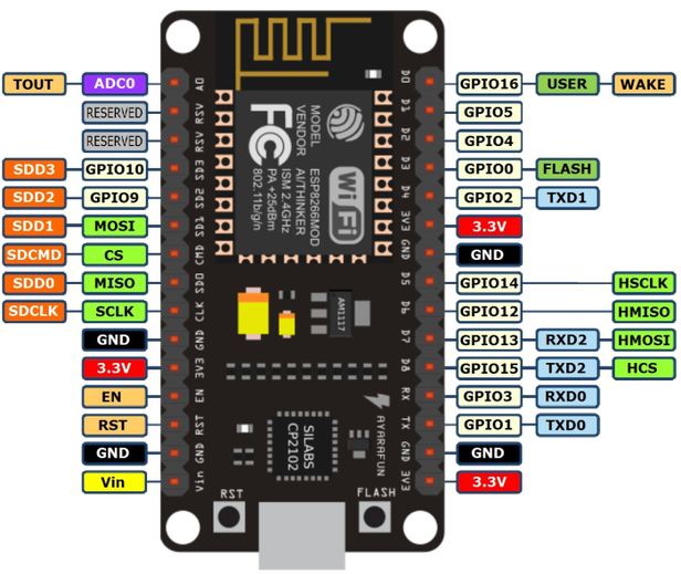
NodeMCU ESP8266
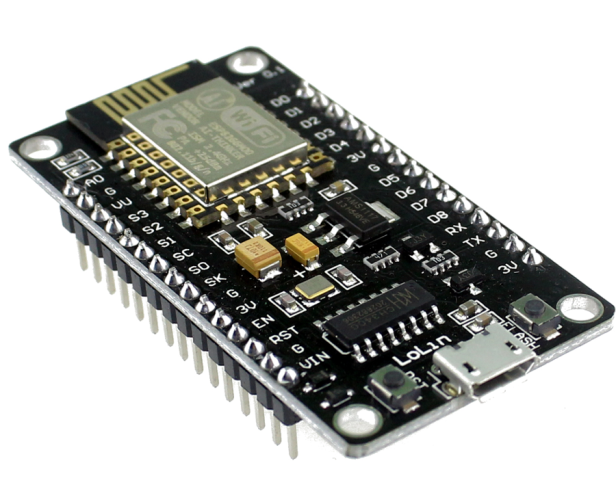
The NodeMCU is one of many ESP8266 modules; any ESP module should work similarly. The pin assignments can be confusing, note the map:
DHT11 Temperature and Humidity Sensor
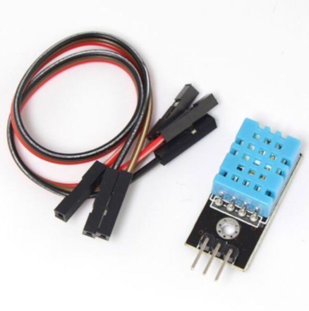
The sensor simply has power, ground and signal. You will need the Adafruit DHT Sensor library.
NodeMCU ESP Sensor Circuit
Getting started with NodeMCU modules
My code for ESP1 (Note, I gave my Raspberry Pi Node-Red server a static IP of 192.168.1.152; and you will need to fill in your WiFi network’s router name (ssid) and password).
1 2 3 4 5 6 7 8 9 10 11 12 13 14 15 16 17 18 19 20 21 22 23 24 25 26 27 28 29 30 31 32 33 34 35 36 37 38 39 40 41 42 43 44 45 46 47 48 49 50 51 52 53 54 55 56 57 58 59 60 61 62 63 64 65 66 67 68 69 70 71 72 73 74 75 76 77 78 79 80 81 82 83 84 85 86 87 88 89 90 91 92 93 94 95 96 97 98 99 100 101 102 103 104 105 106 107 108 109 110 111 112 113 114 | /*****ESP1_Office.inoAdded temp and humidityAll the resources for this project:*****/// Loading the ESP8266WiFi library and the PubSubClient library#include <ESP8266WiFi.h>#include <PubSubClient.h>#include "DHT.h"// Uncomment one of the lines bellow for whatever DHT sensor type you're using!#define DHTTYPE DHT11 // DHT 11//#define DHTTYPE DHT21 // DHT 21 (AM2301)//#define DHTTYPE DHT22 // DHT 22 (AM2302), AM2321// Change the credentials below, so your ESP8266 connects to your routerconst char* ssid = "XXXXXXXXXX";const char* password = "xxxxxxxxxxx";// Change the variable to your Raspberry Pi IP address, so it connects to your MQTT brokerconst char* mqtt_server = "192.168.1.152";// Initializes the espClient. You should change the espClient name if you have multiple ESPs running in your home automation systemWiFiClient esp1Client;PubSubClient client(esp1Client);// DHT Sensorconst int DHTPin = 0;// Initialize DHT sensor.DHT dht(DHTPin, DHTTYPE);// Timers auxiliar variableslong now = millis();long lastMeasure = 0;// Connect an LED to each GPIO of your ESP8266const int ledGPIO2 = 2;const int ledGPIO5 = 5;// Don't change the function below. This functions connects your ESP8266 to your routervoid setup_wifi() {delay(10);// We start by connecting to a WiFi networkSerial.println();Serial.print("Connecting to ");Serial.println(ssid);WiFi.begin(ssid, password);while (WiFi.status() != WL_CONNECTED) {delay(500);Serial.print(".");}Serial.println("");Serial.print("WiFi connected - ESP IP address: ");Serial.println(WiFi.localIP());}// This functions is executed when some device publishes a message to a topic that your ESP8266 is subscribed to// Change the function below to add logic to your program, so when a device publishes a message to a topic that// your ESP8266 is subscribed you can actually do somethingvoid callback(String topic, byte* message, unsigned int length) {Serial.print("Message arrived on topic: ");Serial.print(topic);Serial.print(". Message: ");String messageTemp;for (int i = 0; i < length; i++) { Serial.print((char)message[i]); messageTemp += (char)message[i]; } Serial.println(); // Feel free to add more if statements to control more GPIOs with MQTT // If a message is received on the topic home/office/esp1/gpio2, you check if the message is either 1 or 0. Turns the ESP GPIO according to the message if(topic=="home/office/esp1/gpio2"){ Serial.print("Changing GPIO 2 to "); if(messageTemp == "1"){ digitalWrite(ledGPIO2, HIGH); Serial.print("On"); } else if(messageTemp == "0"){ digitalWrite(ledGPIO2, LOW); Serial.print("Off"); } } if(topic=="home/office/esp1/gpio5"){ Serial.print("Changing GPIO 5 to "); if(messageTemp == "1"){ digitalWrite(ledGPIO5, HIGH); Serial.print("On"); } else if(messageTemp == "0"){ digitalWrite(ledGPIO5, LOW); Serial.print("Off"); } } Serial.println(); } // This functions reconnects your ESP8266 to your MQTT broker // Change the function below if you want to subscribe to more topics with your ESP8266 void reconnect() { // Loop until we're reconnected while (!client.connected()) { Serial.print("Attempting MQTT connection..."); // Attempt to connect if (client.connect("ESP1_Office")) { Serial.println("connected"); // Subscribe or resubscribe to a topic // You can subscribe to more topics (to control more LEDs in this example) client.subscribe("home/office/esp1/gpio5"); client.subscribe("home/office/esp1/gpio2"); } else { Serial.print("failed, rc="); Serial.print(client.state()); Serial.println(" try again in 5 seconds"); // Wait 5 seconds before retrying delay(5000); } } } // The setup function sets your ESP GPIOs to Outputs, starts the serial communication at a baud rate of 115200 // Sets your mqtt broker and sets the callback function // The callback function is what receives messages and actually controls the LEDs void setup() { pinMode(ledGPIO2, OUTPUT); pinMode(ledGPIO5, OUTPUT); dht.begin(); Serial.begin(115200); setup_wifi(); client.setServer(mqtt_server, 1883); client.setCallback(callback); } // For this project, you don't need to change anything in the loop function. // Basically it ensures that you ESP is connected to your broker void loop() { if (!client.connected()) { reconnect(); } if(!client.loop()) client.connect("ESP1_Office"); now = millis(); // Publishes new temperature and humidity every 30 seconds if (now - lastMeasure > 30000) {lastMeasure = now;// Sensor readings may also be up to 2 seconds 'old' (its a very slow sensor)float h = dht.readHumidity();// Read temperature as Celsius (the default)float t = dht.readTemperature();// Read temperature as Fahrenheit (isFahrenheit = true)float f = dht.readTemperature(true);// Check if any reads failed and exit early (to try again).if (isnan(h) || isnan(t) || isnan(f)) {Serial.println("Failed to read from DHT sensor!");return;}// Computes temperature values in Celsiusfloat hic = dht.computeHeatIndex(t, h, false);static char temperatureTemp[7];dtostrf(hic, 6, 2, temperatureTemp);// Uncomment to compute temperature values in Fahrenheit//float hif = dht.computeHeatIndex(f, h);//static char temperatureTemp[6];//dtostrf(hic, 6, 2, temperatureTemp);static char humidityTemp[7];dtostrf(h, 6, 2, humidityTemp);// Publishes Temperature and Humidity valuesclient.publish("home/office/esp1/temperature", temperatureTemp);client.publish("home/office/esp1/humidity", humidityTemp);Serial.print("Humidity: ");Serial.print(h);Serial.print(" %\t Temperature: ");Serial.print(t);Serial.print(" *C ");Serial.print(f);Serial.print(" *F\t Heat index: ");Serial.print(hic);Serial.println(" *C ");// Serial.print(hif);// Serial.println(" *F");}} |
For NodeMCU modules ESP2 and ESP3 remember to change the topics, client.connects in all locations to match what is in the matrix up top.
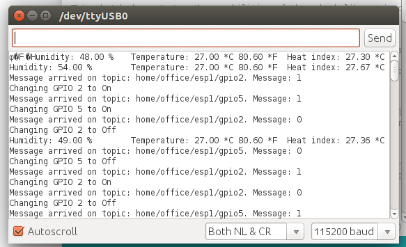
Serial Monitor Messages
While the NodeMCU is plugged into your programming laptop, you can see the serial monitor messages from the Arduino IDE for troubleshooting:
Preliminary Raspberry Pi Setup
My basic Pi set up for static IP, WiFi, etc.
My Node-Red Setup to install MQTT/Mosquitto Broker
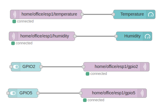
Node-Red Setup
On your Node-Red desktop (mine is 192.168.1.152:1880) you will need to set up your flows for each NodeMCU module in your network. I put each on a different page tab (ESP1 on tab 1, ESP2 on tab 2, etc.) The detailed setup is here: Link
On the Node-Red Dashboard (192.168.1.152:1880/ui) you should have several pages to select:
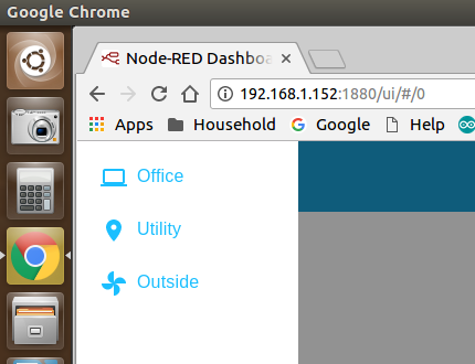
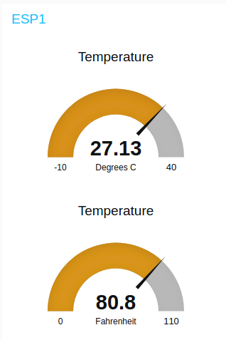
Office should display ESP1:
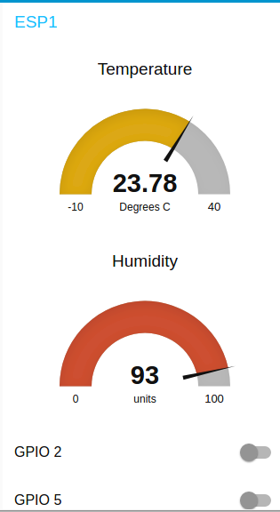
I have a hard time relating to Centigrade temperature; so I modified the flow to include a little JS conversion:
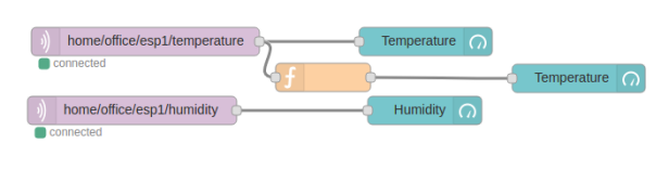
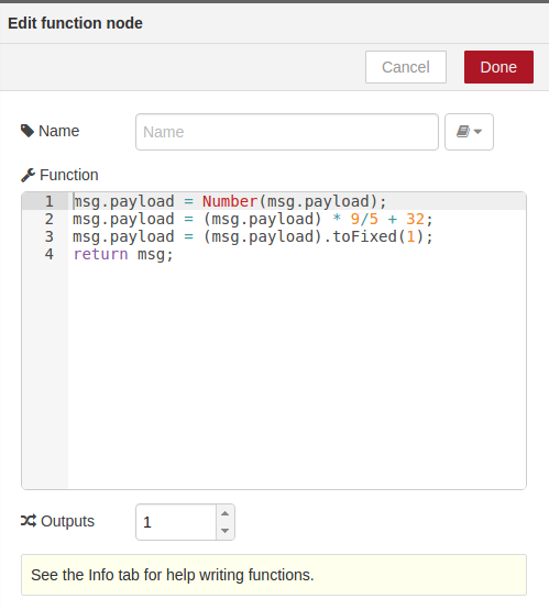
With the result:
I am very pleased with how this project turned out. I plan on adding more sensors; using SONOFF modules for home automation, and to work out security issues and tunneling in order to control my network from afar. Node-Red has turned out to be a fantastic platform to explore all of this.

沒有留言:
張貼留言