Arduino – Controlling a WS2812 LED strand with NeoPixel or FastLED
Difference between WS2801, WS2811 and WS2812
Before we start, we should probably identify the differences between the WS2801, WS2811 and WS2812 based strips (also called “strands”).
Most projects and descriptions out there discus these sometimes mixed, and for one who dives into LED strips for the first time, these models numbers might be confusing.
The model numbers WS2801, WS2811 and WS2812 actually refer to different “things”.
The WS2801 and WS2811 are LED driver IC’s (Integrated Circuits).
These IC’s can control up to 3 LEDs, typically Red, Green and Blue. Positioned close together, so you as a viewer will see the mixed color result.
The WS2801 used to be quite popular but the WS2812/WS2811 appears to be taking over the reigns.
The WS2812 however is a WS2811 placed inside a 5050 LED package.
The 5050 LED is a very common 3 LED (Red, Green, Blue) package, in one 5mm x 5mm case.
A WS2812 is the same package but with an additional WS2811 LED driver IC on board.
In the illustration below you’ll see the difference:
On the left a 5050 RGB LED, on the right a WS2812 which combines a 5050 RGB LED with a WS2811 controller.
Note how the layout of the “silver” tracks are almost identical in both images, yet the black (IC) block and the tiny wires are different (right).
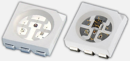
5050 RGB LED (left) and WS2812 (right)
Where the WS2801 strips needed 4 wires, the WS2811/WS2812 strips only needs 3 wires. The WS2801 uses a separate clock line, which can be seen as an advantage, whereas the WS2811/WS2812 does not. The WS2811/WS2812 depends on sending data matching a very tight timing. The advantage of the WS2812 though, is that production of these combo’s in strips is easier and therefor cheaper, and each RGB LED takes much less space on strips.
Your selection here depends on what type of microcontroller you’ll be using and which of these are supported by the application or library you intend to use.
For example, Arduino based projects work fine with any of these, since everything runs real-time.
When using a Raspberry Pi however, using a WS2811/WS2812 can be a little bit more challenging due to the strict timing needs. A Raspberry Pi typically runs Linux, which is not a so-called Real-time Operating System, where intended timing might be disrupted by other background activities.
In my little Arduino project I’ll be using the WS2812.
Specifications
I have made the spec sheets of the 5050 LED, WS2801, WS2811 and WS2812 available as PDF:
– WS2801 Spec Sheet
– WS2811 Spec Sheet
– WS2812 Spec Sheet
– 5050 LED Spec Sheet
These spec sheets can also be downloaded with all 4 PDF’s bundled in a single ZIP file:
DOWNLOAD - WS28xx LED Specification Sheets
| Filename: | LED-Specification-sheets.zip |
| Platform: | Undefined |
| Version: | |
| Size: | 1.1 MB |
| Date: | 2014-01-03 |
Direct reference link: https://www.tweaking4all.com/downloads/LED-Specification-sheets.zip | |
| Download Now | |
LED strips Differences
Now that we know the difference between the model numbers, let’s look at a few examples of LED strips.
There are 2 major types of LED strips that support multiple colors: Analog strips and Digital strips.
For our project we want DIGITAL RGB LED stripS … not the analog ones.
ANALOG LED STRIPS
These are NOT the kind of LED strips we use in this project!
In the illustration below we see first (top) a strip of single color LED’s – typically white, but can be purchased in different colors. The one below that is a multicolor strip (RGB pins are a give away) which allows us to set the color for the entire strip.
On each of these strips you’ll see (from left to right) first the LED as a white block, followed by an SMD resistor as a tiny back block.
The examples below require 12V to operate.
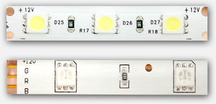
Analog LED strips – Single color (top), Multicolor (bottom)
DIGITAL RGB LED strips
The digital strips are the ones we will use in this project.
In particular: we will use the WS2812 in our project.
The cool part of a digital strip is that you address each LED individually, making very cool effects easy. Obviously the kind we’d like to use in our projects.
In the illustration below you can see the physical differences between the WS2801 and the WS2811/WS2812 strips.
Unlike the analog strips: Most Digital RGB strips operate on 5 Volts!
Note:
- Not all strips of the same “model”, look the same, but have typically a very similar layout.
- strips can be sold as a white or a black strip (background strip).
- Notice the arrows indicating Data direction.
- WS2801 has 4 pins, where as the WS2811/WS2812 only has 3 pins.
- There are digital strips that look like WS2801/WS2811/WS2812 strip, that are NOT based on any of these LED drivers.
- Strips can be had in waterproof (in plastic “tube”) or for indoor use only.
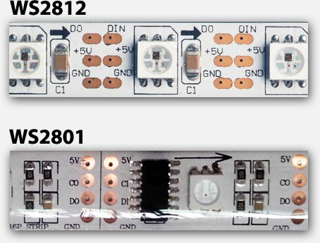
Digital LED strip – WS2812 (top) and WS2801 (bottom)
| PIN | WS2801 | WS2812 |
|---|---|---|
| 5V | Power (+5V) | Power (+5V) |
| CI | Clock signal Input | N/A |
| CO | Clock signal Output | N/A |
| DI | Data Input | Data Input |
| DO | Data Output | Data Output |
| GND | Ground or Common | Ground or Common |
Data Flow
As you can see in the images above:
A 5050 RGB LED + LED Driver IC combo makes a single “unit”.
For the WS2801 this is an IC and a 5050, for the WS2812 this is a single component holding a 5050 LED and WS2811 combined.
These units are chained and each have an input side and an output side. The arrow printed on the strip indicates the data flow direction.
Each output of the previous unit is connected to the input of the following unit, and that’s why we see in the little table INPUT and OUTPUT designated pins.
It’s important to pay attention to the arrow, if you use your strip in the wrong “direction”, it will not work.
Note : Simply connecting +5V and GND will at best flash up your strip for a fraction of a second.
The LEDs need to be “told” to be ON, so without data feed your LEDs will remain OFF.
Time to order a WS2812 RGB LED Strip …
Now that we know the basics and the things to look for, you should be able to order the right strip. Keep in mind that often WS2812 strips are offered as WS2811 strips – different name, same thing. Some sellers mention WS2801 in their product name or advertisement – please make absolutely sure you’re getting the WS2811/WS2812.
Both Amazon and eBay are good resources, and some report positive results with Alibaba … I’ve never ordered from Alibaba, and your milage may vary.
One of my favorite places is AdaFruit, which is not just any random shop, as they provide awesome information when it comes to Arduino projects and the likes.
Making the Arduino WS2812 connection
Now that we have a WS2812 strip, time to hook it up to our Arduino (I used an Arduino UNO for this).
Power
Caution
A strip of LED’s will pull way too much power for your Arduino to handle, so always consider an additional 5V power supply.
Rule of thumb is : each RGB LED unit pulls about 60 mA (3x 20 mA, for Red, Green and Blue).
LED’s, even though they’re called power efficient, do need juice … and for each WS2812 we need up to 60 mA when the 3 LEDs inside are at maximum brightness at 5V.
Power Supply
You can use an external power supply for this purpose and even though my 1 meter strip theoretically needs 3.6 A at max brightness, my little 2A power supply managed to handle it – your milage may vary! (1 meter with 60 LEDs/meter = 60 * 60 mA = 3600 mA = 3.6 A max.)
A switching power supply is often ideal and pretty cheap – you might even have one or the other laying around from your old cellphone, just make sure it’s actually giving you 5 – 6V and not weird voltages like 12V or 16V or even more. Verification with a Voltage meter is recommended.
Batteries
You can consider using batteries, although I’m not a big fan of using them. With batteries please pay attention to the voltage sum.
Consider:
– 3 x Alkaline AA batteries (4.5 V) or
– 4 x NiMH AA rechargeable batteries (4.8 V)
About Amps and such
Like I mentioned before, each LED module takes a max of 60 mA, so you can calculate how many Amps your power source has to provide. Keep in mind that 1000 mA = 1 A.
Your power supply can have overcapacity when it comes to Amps, so if your project needs 3.6 A, and you only have a 10 A power supply, then this will work great.
Keep in mind though that the Voltage must be close to the 5V value. Higher voltages may damage your LEDs.
Connecting Arduino and WS2812 strip
The basic layout of power can be done in 2 ways – with computer or without …
Arduino Connected to your Computer
Commonly, during testing, your Arduino is connected to your computer via a USB cable where the USB cable does not only program the microcontroller but will also provide power for the Arduino.
The DIN (data input) pin of the LED strip goes to Arduino PIN 6 with an optional 470Ω resistor in between.
+5V of the LED strip goes to the +5V of extra power supply.
GND of the LED strip goes to GND of the extra power supply and to the GND of the Arduino.
The USB of the Arduino is connected to your computer.
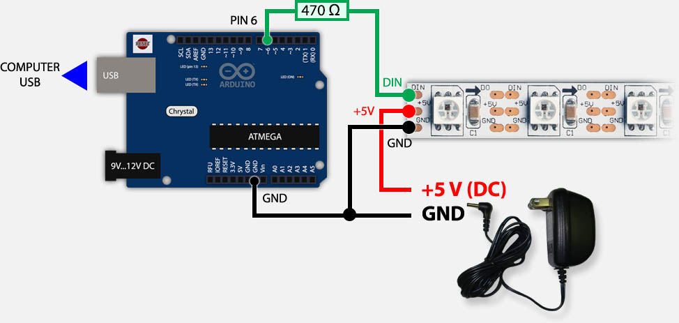
Arduino & WS2812 – USB and External Power
Arduino Not connected to your computer
Once you’ve completed your prototyping, you could still keep using your Arduino for controlling the LED strip.
In that case you’d typically have the Arduino in a very different location, and thus not connected to your computer. In that case the extra power supply for the LEDs could be used to feed the Arduino as well.
The DIN (data input) pin of the LED strip goes to PIN 6 of the Arduino with an optional 470Ω resistor in between.
+5V of the LED strip goes to the +5V of extra power supply and the +5V on your Arduino (or Vin).
GND of the LED strip goes to GND of the extra power supply and to the GND of the Arduino.
Power connected to +5V or Vin?
In the drawing below, you’ll notice that I have used +5V pin for the powersupply.
This works well when you’re using a proper and well regulated powersupply, which I do.
For all correctness, and when using less regulated powersupplies, the Vin pin is recommended.
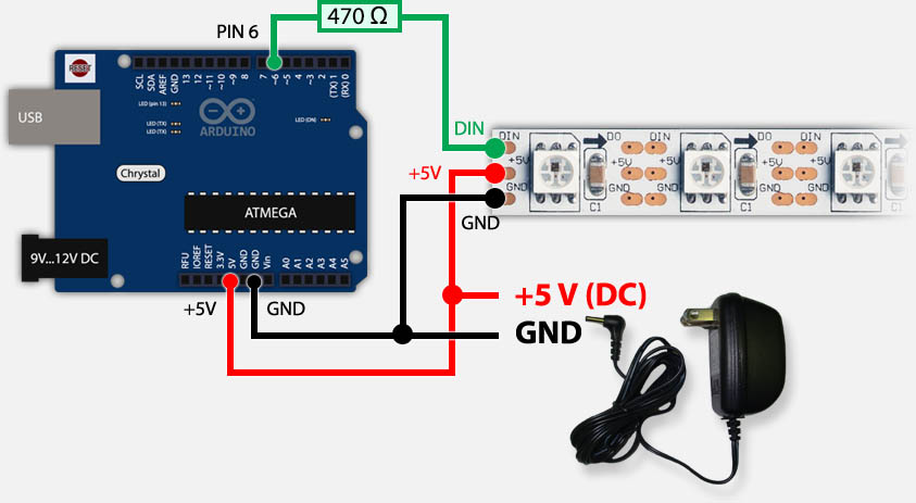
Arduino & WS2812 – Only running on external power supply
Programming the Arduino for WS2811/WS2812
Now that we know how to connect the strip to our Arduino, time to get some cool effects going.
We could of course dig into all the timing details of the WS2811/WS2812 but there are already very good libraries out there that do the difficult work for us.
The most used at this moment are FastLED (successor of FastSPI_LED and FastSPI_LED2) and NeoPixel (by AdaFruit). I’ve added some demo videos, and even though it might give you the impression that NeoPixel could be slower, rest assure, it’s not.
Both Libraries are very good and very fast.
Note : If you haven’t already installed the regular Arduino software, please consider looking at “My First Arduino Project” for details and downloads or download links.
AdaFruit NeoPixel
For no obvious reason, I started my first test with NeoPixel by AdaFruit.
The NeoPixel Library for Arduino can be downloaded from Github or through this direct link (zip file) or from Tweaking4All. As usual I HIGHLY recommend getting the files directly from the source as the version on Tweaking4All might be outdated and only serves as a backup.
DOWNLOAD - Adafruit NeoPixel
| Filename: | Adafruit-NeoPixel.zip |
| Platform: | Undefined |
| Version: | |
| Size: | 27.2 kB |
| Date: | 2014-01-03 |
Direct reference link: https://www.tweaking4all.com/downloads/Adafruit-NeoPixel.zip | |
| Download Now | |
If you downloaded the Tweaking4All ZIP file, then in the Arduino Software simple choose “Sketch” “Import Library…” “Add Library…” and in the file dialog select the downloaded ZIP file. This will automatically install the library for you (requires Arduino 1.0.5 or newer).
If you however downloaded the official version and this trick did give you an error message, the copy then copy the files from the ZIP archive into a folder called “AdaFruit_NeoPixel” in your Arduino Library directory. More details can be found on the Arduino page concerning Libraries.
- Windows:
My Documents\Arduino\libraries\ - MacOS X:
~/Documents/Arduino/libraries/ - Linux:
~/Documents/Arduino/libraries/
After installing the Library, close and restart the Arduino software so that the examples are not visible in the menu.
The first example I ran was of course striptest to see if my LED strips worked alright – choose from the menu “File” “Examples” “AdaFruit_NeoPixel” “striptest“.
Before compiling and uploading the sketch to your Arduino, first verify some basic settings in the code.
– line 3 : make sure #define PIN 6 is actually matching the pin number you’ve used on your Arduino
– line 12 : make sure the first parameter in Adafruit_NeoPixel(60, ... matches the number of LED’s in your strip (here: 60).
If you used the wiring schematics shown earlier then PIN 6 would be the right pin. Click the “Upload” button, wait a few seconds and see the magic at work.
Here a short video of the NeoPixel demo – I didn’t do too much effort as you can see, but it gives you an idea ….
2
3
4
5
6
7
8
9
10
11
12
13
14
#define PIN 6
// Parameter 1 = number of pixels in strip
// Parameter 2 = pin number (most are valid)
// Parameter 3 = pixel type flags, add together as needed:
// NEO_KHZ800 800 KHz bitstream (most NeoPixel products w/WS2812 LEDs)
// NEO_KHZ400 400 KHz (classic 'v1' (not v2) FLORA pixels, WS2811 drivers)
// NEO_GRB Pixels are wired for GRB bitstream (most NeoPixel products)
// NEO_RGB Pixels are wired for RGB bitstream (v1 FLORA pixels, not v2)
Adafruit_NeoPixel strip = Adafruit_NeoPixel(60, PIN, NEO_GRB + NEO_KHZ800);
...
I highly recommend snooping through the code of this example, make some changes, see what happens.
The full code can be found below.
Pay attention to these functions:
2
3
4
5
6
strip.show(); // Update all LEDs (= turn OFF, since none of them have been set yet!)
...
c = strip.Color(255, 0, 0); // define the variable c as RED (R,G,B)
strip.setPixelColor(10, c); // set LED 10 to the color in variable c (red)
strip.show(); // Update all LEDs (= make LED 10 red)
It’s worth playing with for a bit to get familiar with how things are being called.
Note : To switch a LED off use the color BLACK (strip.Color(0,0,0)).
2
3
4
5
6
7
8
9
10
11
12
13
14
15
16
17
18
19
20
21
22
23
24
25
26
27
28
29
30
31
32
33
34
35
36
37
38
39
40
41
42
43
44
45
46
47
48
49
50
51
52
53
54
55
56
57
58
59
60
61
62
63
64
65
66
67
68
69
70
71
72
73
74
75
76
77
78
79
80
81
82
83
84
85
86
87
88
89
90
91
92
93
94
95
96
97
98
99
100
101
102
103
104
105
106
107
108
109
110
111
112
113
114
115
116
117
#define PIN 6
// Parameter 1 = number of pixels in strip
// Parameter 2 = pin number (most are valid)
// Parameter 3 = pixel type flags, add together as needed:
// NEO_KHZ800 800 KHz bitstream (most NeoPixel products w/WS2812 LEDs)
// NEO_KHZ400 400 KHz (classic 'v1' (not v2) FLORA pixels, WS2811 drivers)
// NEO_GRB Pixels are wired for GRB bitstream (most NeoPixel products)
// NEO_RGB Pixels are wired for RGB bitstream (v1 FLORA pixels, not v2)
Adafruit_NeoPixel strip = Adafruit_NeoPixel(60, PIN, NEO_GRB + NEO_KHZ800);
void setup() {
strip.begin();
strip.show(); // Initialize all pixels to 'off'
}
void loop() {
// Some example procedures showing how to display to the pixels:
colorWipe(strip.Color(255, 0, 0), 50); // Red
colorWipe(strip.Color(0, 255, 0), 50); // Green
colorWipe(strip.Color(0, 0, 255), 50); // Blue
// Send a theater pixel chase in...
theaterChase(strip.Color(127, 127, 127), 50); // White
theaterChase(strip.Color(127, 0, 0), 50); // Red
theaterChase(strip.Color( 0, 0, 127), 50); // Blue
rainbow(20);
rainbowCycle(20);
theaterChaseRainbow(50);
}
// Fill the dots one after the other with a color
void colorWipe(uint32_t c, uint8_t wait) {
for(uint16_t i=0; i<strip.numPixels(); i++) {
strip.setPixelColor(i, c);
strip.show();
delay(wait);
}
}
void rainbow(uint8_t wait) {
uint16_t i, j;
for(j=0; j<256; j++) {
for(i=0; i<strip.numPixels(); i++) {
strip.setPixelColor(i, Wheel((i+j) & 255));
}
strip.show();
delay(wait);
}
}
// Slightly different, this makes the rainbow equally distributed throughout
void rainbowCycle(uint8_t wait) {
uint16_t i, j;
for(j=0; j<256*5; j++) { // 5 cycles of all colors on wheel
for(i=0; i< strip.numPixels(); i++) {
strip.setPixelColor(i, Wheel(((i * 256 / strip.numPixels()) + j) & 255));
}
strip.show();
delay(wait);
}
}
//Theatre-style crawling lights.
void theaterChase(uint32_t c, uint8_t wait) {
for (int j=0; j<10; j++) { //do 10 cycles of chasing
for (int q=0; q < 3; q++) {
for (int i=0; i < strip.numPixels(); i=i+3) {
strip.setPixelColor(i+q, c); //turn every third pixel on
}
strip.show();
delay(wait);
for (int i=0; i < strip.numPixels(); i=i+3) {
strip.setPixelColor(i+q, 0); //turn every third pixel off
}
}
}
}
//Theatre-style crawling lights with rainbow effect
void theaterChaseRainbow(uint8_t wait) {
for (int j=0; j < 256; j++) { // cycle all 256 colors in the wheel
for (int q=0; q < 3; q++) {
for (int i=0; i < strip.numPixels(); i=i+3) {
strip.setPixelColor(i+q, Wheel( (i+j) % 255)); //turn every third pixel on
}
strip.show();
delay(wait);
for (int i=0; i < strip.numPixels(); i=i+3) {
strip.setPixelColor(i+q, 0); //turn every third pixel off
}
}
}
}
// Input a value 0 to 255 to get a color value.
// The colours are a transition r - g - b - back to r.
uint32_t Wheel(byte WheelPos) {
if(WheelPos < 85) {
return strip.Color(WheelPos * 3, 255 - WheelPos * 3, 0);
} else if(WheelPos < 170) {
WheelPos -= 85;
return strip.Color(255 - WheelPos * 3, 0, WheelPos * 3);
} else {
WheelPos -= 170;
return strip.Color(0, WheelPos * 3, 255 - WheelPos * 3);
}
}
FastLED (FastSPI_LED)
FastLED is the successor of FastSPI_LED and FastSPI_LED2. According to it’s maintainer(s) the name changed to FastLED since it’s no longer just focussing in SPI LED strips like the one we’re using in our project (WS2811/WS2812). Some older chipsets have been dropped so for older LED strips (non WS2801-WS2812) might want to resort to the older FastSPI_LED2 library.
To download the library you can either click the “Download ZIP” button on the FastLED GitHub page, click this link to directly download the ZIP file, or download a snapshot from Tweaking4All. As usual: we highly recommend getting the files from the source … the Tweaking4All version is only here as a backup and is most likely outdated.
DOWNLOAD - FastLED
| Filename: | FastLED.zip |
| Platform: | Undefined |
| Version: | 3.1 |
| Size: | 275 kB |
| Date: | 2015-09-12 |
Direct reference link: https://www.tweaking4all.com/downloads/FastLED.zip | |
| Download Now | |
If you downloaded the Tweaking4All ZIP file, then in the Arduino Software simple choose “Sketch” “Import Library…” “Add Library…” and in the file dialog select the downloaded ZIP file. This will automatically install the library for you (requires Arduino 1.0.5 or newer).
If you however downloaded the official version and this trick did give you an error message, then copy the files from the ZIP archive into a folder called “FastLED” in your Arduino Library directory. More details can be found on the Arduino page concerning Libraries.
- Windows:
My Documents\Arduino\libraries\ - MacOS X:
~/Documents/Arduino/libraries/ - Linux:
~/Documents/Arduino/libraries/
After installing the Library, close and restart the Arduino software so that the examples are not visible in the menu.
The first example I tried was “testleds” only to find out that it was a left over from FastSPI_LED and did not run. So I updated the code to work with FastLED, you can copy and paste it into the Arduino editor.
Make sure to verify the following lines:
– line 3: make sure you set the number of LEDs right in #define NUM_LEDS 60
– line 8: make sure the correct PIN is set in #define PIN 6
Here you will see that the NeoPixel demo was maybe cooler, but the code for FastLED appears shorter. In the end both Libraries are solid, so pick which you prefer.
As with the NeoPixel code – I highly recommend snooping through the code, modify a few things and see what it does and such. It’s actually fun to do.
Here a video of what the demo does – I didn’t take too much effort to do a perfect video, and I didn’t record the entire test, heck I didn’t even take the LED strip out of the zip-lock bag … ![]()
Addressing LEDs with FastLED works a little different but one could see it as much easier … personal preference … for a list of pre-defined colors see the list after the source code.
Note : to switch a LED Off, set the color to Black as such, before calling the show() function: leds[10] = CRGB::Black; .
2
3
4
5
6
7
8
9
FastLED.show(); // Show changes
...
leds[10].r = 255; // set red for LED 10 (Color = Red + Green + Blue)
leds[10].g = 125; // set green for LED 10
leds[10].b = 0; // set blue for LED 10
FastLED.show(); // Show changes
2
3
4
5
6
7
8
9
10
11
12
13
14
15
16
17
18
19
20
21
22
23
24
25
26
27
28
29
30
31
32
33
34
35
36
37
38
39
40
41
42
43
44
45
46
47
48
49
50
51
52
53
54
55
56
57
58
59
60
61
62
63
64
65
66
67
68
69
70
71
72
73
74
75
76
77
78
79
// Number of RGB LEDs in the strand
#define NUM_LEDS 60
// Define the array of leds
CRGB leds[NUM_LEDS];
// Arduino pin used for Data
#define PIN 6
void setup()
{
FastLED.addLeds<NEOPIXEL, PIN, RGB>(leds, NUM_LEDS);
}
void loop() {
// one at a time
for(int j = 0; j < 3; j++) {
for(int i = 0 ; i < NUM_LEDS; i++ ) {
memset(leds, 0, NUM_LEDS * 3);
switch(j) {
case 0: leds[i].r = 255; break;
case 1: leds[i].g = 255; break;
case 2: leds[i].b = 255; break;
}
FastLED.show();
delay(10);
}
}
// growing/receeding bars
for(int j = 0; j < 3; j++) {
memset(leds, 0, NUM_LEDS * 3);
for(int i = 0 ; i < NUM_LEDS; i++ ) {
switch(j) {
case 0: leds[i].r = 255; break;
case 1: leds[i].g = 255; break;
case 2: leds[i].b = 255; break;
}
FastLED.show();
delay(10);
}
for(int i = NUM_LEDS-1 ; i >= 0; i-- ) {
switch(j) {
case 0: leds[i].r = 0; break;
case 1: leds[i].g = 0; break;
case 2: leds[i].b = 0; break;
}
FastSPI_LED.show();
delay(1);
}
}
// Fade in/fade out
for(int j = 0; j < 3; j++ ) {
memset(leds, 0, NUM_LEDS * 3);
for(int k = 0; k < 256; k++) {
for(int i = 0; i < NUM_LEDS; i++ ) {
switch(j) {
case 0: leds[i].r = k; break;
case 1: leds[i].g = k; break;
case 2: leds[i].b = k; break;
}
}
FastLED.show();
delay(3);
}
for(int k = 255; k >= 0; k--) {
for(int i = 0; i < NUM_LEDS; i++ ) {
switch(j) {
case 0: leds[i].r = k; break;
case 1: leds[i].g = k; break;
case 2: leds[i].b = k; break;
}
}
FastLED.show();
delay(3);
}
}
}


沒有留言:
張貼留言