Wiring MOSFET module board on Higher Loads with Motor
In this illustration we will going to wire the IRF520 MOSFET (Metal Oxide Semiconductor Field-effect Transistor) Module Board a simple breakout board for driving higher loads. MOSFET enables you to control higher voltage projects on microcontroller. MOSFET is also kind of a switch that isolate the power from the main load, when the power load to the MOSFET it will pass the power from one to another when closed, but if the outer power source is absent your device can still draw power from microcontroller.
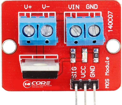
In this illustration we will going to use to MOSFET Module board, we connect the power for the device you want to control to the VIN and GND then connect your control a pump, LED, or other DC device, to V+ and V- up to 24v, and ~5A. You can also power this device from your Arduino to 5v VCC connection and GND pin.
Note: Use only one power source do not plug two power source.
Required Components
Arduino UNO/MEGA/PRO/MINI
MOSFET IRF520 Module Board
12v DC Motor / 24v DC Motor
100k/10k Potentiometer / Variable Resistor
Solder Less Bread Board
Jumper Wires
Motor Suppressor is Optional
MOSFET IRF520 Module Board
12v DC Motor / 24v DC Motor
100k/10k Potentiometer / Variable Resistor
Solder Less Bread Board
Jumper Wires
Motor Suppressor is Optional
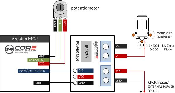
Wiring Diagram
Arduino Sketch Code
Download the Motor Control Library here | Zip


沒有留言:
張貼留言