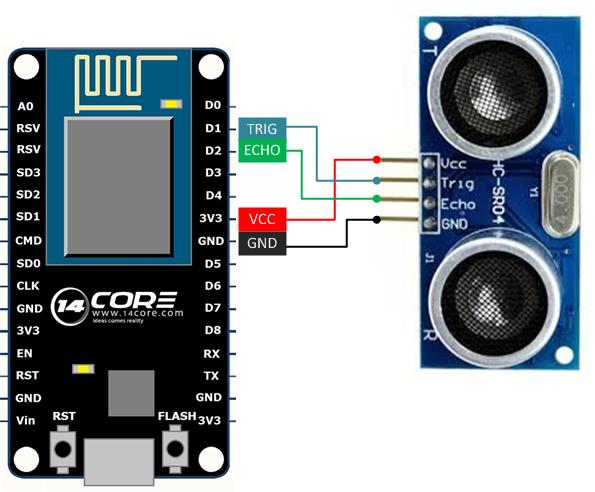
In this illustration we will going to wire the ESP8266 12E nodeMCU with Ultrasonic Raging Sensor HCSR04. As you can see the illustration below the sensor trigger pin is connected to D1 which is pin 5 in Arduino Board, and the ECHO is connected to D2 which is pin 4 in Arduino Board. However in the sketch code we are going to use the Arduino IDE to program the NodeMCU ESP8266 12E Development board if you to have a interpreter in your Arduino IDE please refer to this link.


沒有留言:
張貼留言