Blink LED
To blink the LED we'll connect to the MicroPython board's REPL (read-eval-print loop, like a Python 'command prompt') and run commands that control the digital GPIO connected to the LED. This way we can interactively turn the LED on and off right from the board without uploading any code, sketches, etc.
If your board has built-in LEDs that you can control you'll want to note the pin names or numbers for the LEDs:
- pyboard
- The pyboard has 4 built-in LEDs that you can control. See the pinout diagram here and its note that pins P2-P5 control the LEDs. One important clarification though, when you reference those pins in code you want to use the 'CPU name' in the white box on the diagram and not the pin name in the yellow box. So pin P2 is actually called B4, P3 is A15, etc. All of the LED pin CPU names are:
- B4 = blue LED
- A15 = yellow LED
- A14 = green LED
- A13 = red LED
- Note too on the pyboard pin names are strings like 'B4' for the blue LED. Instead of trying to send a number like 4 to pin functions you'll instead send a string 'B4'.
- Feather HUZZAH ESP8266 and HUZZAH ESP8266 Breakout
- Both the HUZZAH ESP8266 boards have a red LED you can control connected to pin number 0.
If your board doesn't have built-in LEDs make sure you've wired up a LED to one of the digital GPIO pins as shown in the previous page.
Connect to Serial REPL
To get started you'll need to connect to the board's serial REPL so you can send commands to control the LED. Check out the Serial REPL page from this guide for information on tools to connect to the board's REPL. Make sure you can connect to the REPL and see the >>> prompt before continuing!
Control the LED
Now for some excitement, let's turn the LED on and off from MicroPython! The first step is to run a line of code that imports a special MicroPython module called 'machine'. Run the following command at the serial REPL:
- import machine

After pressing enter you should see no output and the >>> prompt return. This just means the command succeeded and the machine module is now imported. Once a module is imported you can access classes, objects, etc. from inside it (just like if you were writing Python code to run on your computer).
If you're curious you can even run a help command to see what objects and things are available in the machine module that was imported:
- help(machine)

We'll use the Pin class to create an object that represents a digital GPIO pin on the board. Once you have an instance of this Pin object you can call functions on it to set it to high and low levels that turn on and off the LED.
First create the Pin instance with a command like the following (note change the pin number, 15 in this example, to the pin number or name for your LED):
- led = machine.Pin(15, machine.Pin.OUT)

Again you shouldn't see any output after running the command, and the REPL prompt should appear again.
Notice how when the Pin object is created it takes two parameters, first the pin number or name and then the function of the pin. A pin can be set as an output which can set its level or voltage to a high or low value (like 'on' or 'off'), or it can be set as an input which can read if it's at a high or low value. To blink the LED we just need to use the pin as an output since we're telling the LED to turn on or off using the level/voltage from the pin.
If you have multiple LEDs connected to the board you can create different Pin objects to control them individually! Use the same syntax as above but create a new object like led2 and set the pin number or name appropriately.
Now for some fun, let's turn the LED on by setting the Pin to a high level with this command:
- led.high()

You should see the LED instantly turn on! There won't be any output from this command either.
Now turn the LED off by calling the low() function on the Pin object:
- led.low()
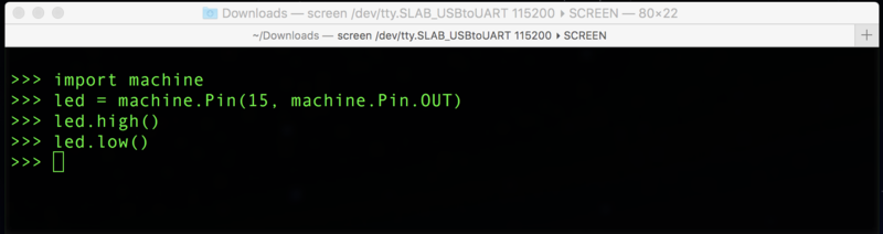
You should see the LED turn off after running the command. Woo hoo you're blinking a LED with MicroPython!
If for some reason your LED doesn't turn on or off with the above commands go back and carefully check all the wiring between the board and LED. Make sure the LED is oriented the right way with the long leg (anode) connected to the board pin and the short leg (cathode) connected through a resistor to the board ground. Also double and triple check you're using the right pin number or name--boards usually have a lot of pins and it's easy to use the wrong one on accident.
Try toggling the LED on and off by running the high and low commands again. In the serial REPL you can actually press the up arrow or down arrow keys to quickly go back to previously run commands.
Add a Loop
Blinking the LED yourself with commands you run manually will get a little tiring after a while. However since MicroPython is really just like desktop Python you can use a Python loop to blink the LED a number of times or even forever.
First you'll want to import the time module so you can use its sleep function to delay for a short time (otherwise the loop would run so fast you couldn't tell the LED is blinking!). Just like importing the machine module you can import time with:
- import time
Now let's use a for loop to blink the LED 10 times on and off. Enter the following code in the REPL, and notice how the REPL changes and starts to indent code inside the loop for you:
- for i in range(10):
- led.high()
- time.sleep(0.5)
- led.low()
- time.sleep(0.5)

After entering the last line, time.sleep(0.5), and pressing enter you'll need to end the indented block by pressing delete and then enter again. At this point the loop will start running and the LED should blink on and off!
Notice as the LED blinks and the loop runs you can't see the >>> REPL prompt or enter any code. This is because MicroPython can only do one thing at a time and running code in a loop like that requires all of the board's attention. Only once the code stops running can MicroPython give you the prompt to enter more code.
Try entering the code again and changing the value of the time.sleep function calls. This function takes in a number that controls how long in seconds the board will delay. You can use decimal values like 0.5 to sleep for half a second. If you increase the value the LED will stay on and off for longer periods and slow down the blinking. Likewise if you decrease it then the LED will blink faster.
Also try changing the number in the range function call that starts the loop. The value 10 means the loop should repeat 10 times, however you can increase or decrease this to control how many times the LED blinks. Every time the loop runs it will run each instruction inside of it in order, so you can see how it starts by turning the LED on, then delaying a bit, turning the LED off, and delaying again. When all the code inside the loop has been run it will go back to the top and run the code again, unless the loop has been run for as long as the range function specified.
For one final example let's use an infinite loop that will blink the LED forever. Enter the following code:
- while True:
- led.high()
- time.sleep(0.5)
- led.low()
- time.sleep(0.5)

Again remember you have to press delete after the last line to end the indented block. Once you run this code the LED should start blinking on and off forever!
You might be worried to see the >>> REPL prompt never appears again and you can't enter code. Remember this is because MicroPython can only do one thing at a time and the infinite loop means the board is busy blinking the LED.
Luckily you can tell the board to stop whatever it's doing and return back to the REPL prompt. Press the Ctrl-c key on your keyboard and you should see the code stop with a KeyboardInterrupt error like this:

This is a handy tip to remember, if you ever need to stop a program that's running on the board just connect to the REPL and press Ctrl-c. Sometimes you might need to press Ctrl-c a few times to stop everything.
That's all there is to blinking a LED with MicroPython! With a few simple commands you can control a LED connected to a board pin. Then using standard Python loop and delay functions you can make MicroPython blink the LED however you desire.
One important note though, you might wonder what happens if you start the LED blinking with a while loop like above and then reset or unplug/plug back in the board. Try it to see what happens!
You might think the board will start up and go back to running the code you entered. However that's not how MicroPython works--any code you enter in the REPL is just run for that moment in time. As soon as you power down the board it will 'forget' what it was doing and start over fresh. You'll see in a later guide how to make the board run a script when it starts, and that way you can make the board run your code like blinking a LED as soon as it powers up.
If you're curious to go further be sure to explore your board's documentation to see what else the machine module and Pin class expose. For example here's the documentation for MicroPython ESP8266 machine module.


