2017年1月6日 星期五

ESP8266–WiFi library on Arduino IDE

源自於
https://alselectro.wordpress.com/2016/11/29/esp8266-wifi-library-on-arduino-ide/

ESP8266–WiFi library on Arduino IDE


In the previous post we’ve seen how to program ESP8266 using Arduino IDE by installing the Boards Manager.
This post is on using the powerful ESP8266 WiFi Library which is automatically installed while using the Boards Manager.When you proceed with the  board package for the ESP8266,as explained in previous post, the ESP8266 WiFi library is automatically installed for you.
             Now, any time you want to use the classes and the functions from that ESP8266 WiFi library,  use the Include statement at the top of the program first, followed by the header name
#include <ESP8266WiFi.h>
at the starting of Arduino code & start using the Classes associated with this library.
ESP8266 WiFi library is designed after the the standard Arduino WiFi library but has even more functionality than the standard Arduino library .The standard Arduino WiFi library is used for the WiFi shield or with the Arduino boards like YUN with inbuilt WiFi.
With the introduction of ESP8266 , the WiFi functionality has become much cheaper & easy to use.
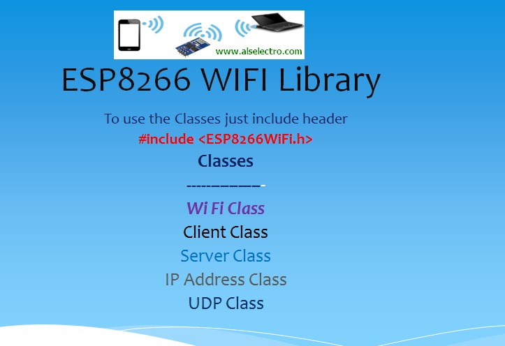
The WiFi library has many classes that you can use. Each class has functions in it that are specific to that class. There’s the WiFi class, the IP address class, the server class, the client class and the UDP class.
class1

In this post we’re going to explore the WiFi class & its functions.
The WiFi class allows to establish a connection with an access point.
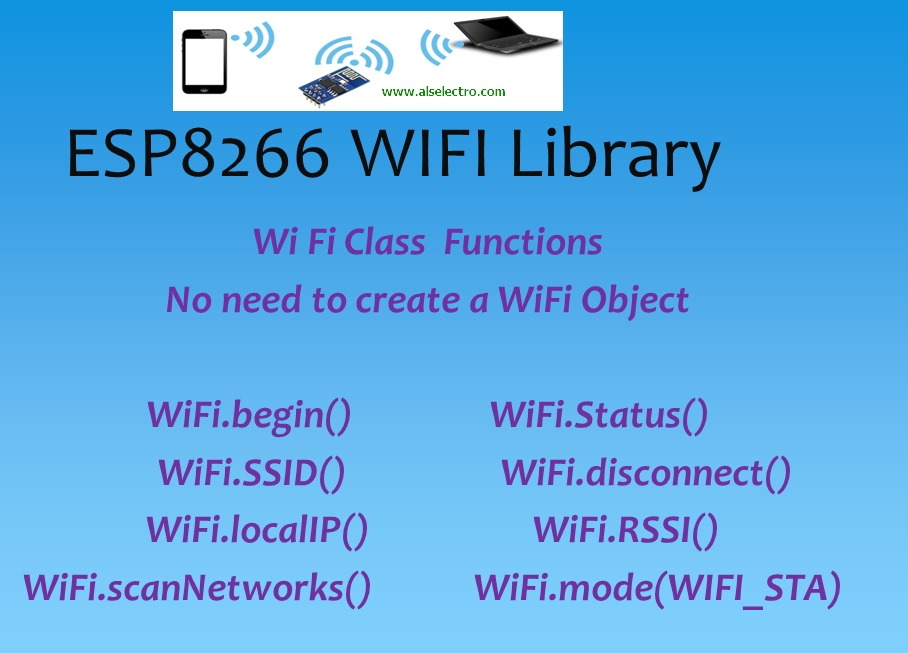
What’s cool about the WiFi class is that we don’t  have to create an instance of this class. We can  go ahead and start using it. It’s like the serial library of Arduino. We don’t need to create an instance of the serial library.
class2

First Function of the library is WiFi.begin().
The usage of this function is similar to our Serial.begin().
Just like Serial.begin() , we use WiFi.begin() .WiFi.begin() requires 2 strings as arguments. You need to pass the SSID and the password of the Access point you wish to connect.You need to pass the arguments as character arrays or strings with a lower case s.
WiFi.begin(ssid,pass);
The possible return values are
WL_CONNECTED      after successful connection is established with the Access Point
WL_IDLE_STATUS       when Wi-Fi is in process of changing between statuses
WL_NO_SSID_AVAIL     in case configured SSID cannot be reached
WL_CONNECT_FAILED  if password is incorrect
WL_DISCONNECTED        if module is not configured in station mode

The status function in the WiFi class, doesn’t take any arguments but it returns stuff depending on the status of the network that you’re connected to.
Usually, first, you call WiFi.begin, you pass the SSID and the password because you’re trying to establish a connection with the network. Then, what you do is you wait in a loop until WiFi.status returns the value WL_CONNECTED.
——————————
WiFi.begin(ssid,password);
while (WiFi.status() != WL_CONNECTED)
{
delay(500);
Serial.print(“.”);
}
——————————

WiFi.SSID();
WiFi.SSID doesn’t take any arguments but it returns the name of the SSID that you’re connected to.

WiFi.RSSI()
Returns the current signal strength in  dB

WiFi.scanNetworks()
Returns the number of discovered networks.It will not list the network names , but returns the number of networks.
WiFi.macAddress()
Returns the MAC address of the ESP device
There is a specific function available to print out key Wi-Fi diagnostic information:
WiFi.printDiag(Serial);
Here is a sample sketch to demonstrate the WiFi library.
—————————————————-
#include <ESP8266WiFi.h>
void setup()
{
  Serial.begin(115200);
  Serial.println();
//disconnect any previous connections
  WiFi.disconnect();
  delay(1000);
//scan for number of nearby networks & print SSIDs
  Serial.print("Nearbyorks found  :");
  Serial.println(WiFi.scanNetworks());
  delay(500);
Serial.println("List of surrounding Network SSIDs…:");
  int n = WiFi.scanNetworks();
  for (int i = 0; i < n; i++)
{
  Serial.println(WiFi.SSID(i));
}
  Serial.println();
//connect to preferred SSID
  
  WiFi.begin("SARAVANA-ACTypass123");
  Serial.println("Connecting");
  while (WiFi.status() != WL_CONNECTED)
  {
    delay(500);
    Serial.print(".");
  }
  Serial.println();
// print SSID name,local IP allotted ,MAC address & signal strength
  Serial.println();
  Serial.print("ConnectedSID          : ");
  Serial.println(WiFi.SSID());
  Serial.print("IPess allotted to ESP : ");
  Serial.println(WiFi.localIP());
 
  Serial.print("MACess of ESP         : ");
  Serial.println(WiFi.macAddress());
  Serial.print("Signalngth is         : ");
  Serial.println(WiFi.RSSI());
  }
void loop()
{
}
——————————————————–
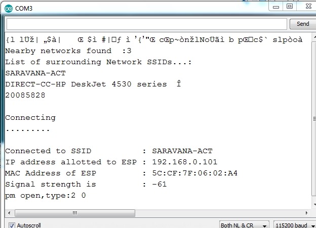
The screenshot shows the result in the serial monitor of Arduino IDE
scan3

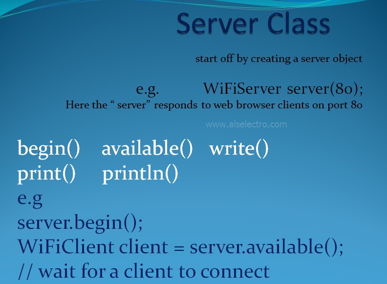
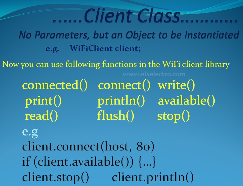
The Client & Server classes & their methods are shown in screen shots below :
class3


class4
Download PDF tutorial file for the WiFi library from

IOT Demo with ESP8266 WiFi IOT ESP8266 ESP-12 Test Board

源自於
https://alselectro.wordpress.com/2016/06/27/home-automation-iot-demo-with-esp8266-wifi-iot-test-board/

Home Automation–IOT Demo with ESP8266 WiFi IOT Test Board


Image 2

Image 1

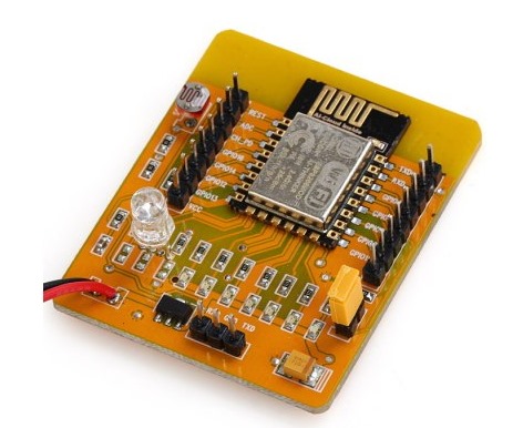
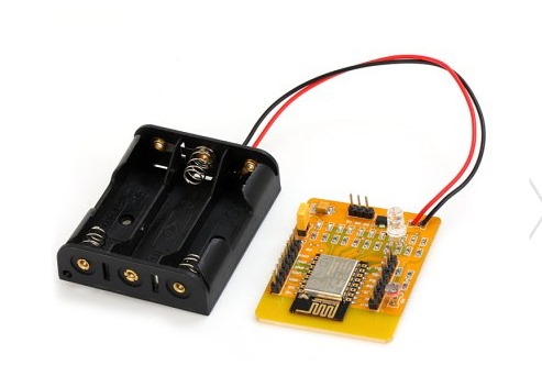
Introducing a new ESP8266 Development Board with an ESP-12, a 3x AA battery holder, a voltage regulator, an RGB LED, several red LEDs, and a light sensor LDR on the ADC input all on one board.
The board can be controlled by an open source Android App which is available from the AI-THINKER Website.
GPIO pins are extended with berg pins for easy external connections. RXD,TXD & GND pins are provided for programming / firmware upgrading. A yellow jumper is provided to pull GPIO0 pin to GND during programming. During normal operation this jumper must be removed.
The board is powered by 3 nos AA batteries , for which a battery box is already wired. On board 3.3v regulator is provided for a stable power supply.
No power switch or Reset switch is provided. To switch off you need to pull out one of the batteries.
The board comes pre-loaded with a demo which does actually seem to work.  If you have an Android based phone or tablet you can download AI-Thinker’s app to control and mix the color balance on the RGB LED and to switch the other LEDs on and off.
The Android Application can be downloaded from :

There are also 6 red LEDs fixed with the necessary resistors connected to GPIO16, GPIO14, GPIO5, GPIO4, GPIO0 and GPIO2. A BLUE LED is always ON if the board is powered.
The GPIO13, GPIO12 and GPIO15 are connected to a RGB LED which allows you color mixing using PWM.
ADC
The analog-digital converter is also available on a pin & connected to a light resistor. This lets you quickly test the ADC and you still can clip the resistor off if you want to measure another analog source.Remember the range of ADC is max 1v & not 0 to 3.3v
If you don’t want to use the light sensor or the LEDs you can simply clip them off. Then you’ll just have an  ESP8266 with 3xAA power supply, 9 available GPIO pins and one ADC.
On the playstore of your Android device search for  IOT DEMO App & install it.
Open the Settings & enable WIFI of the Android phone.Now power on the ESP board to see the AI-THINKER SSID on your mobile.
PAIR this with the ESP board using password ai-thinker
Now open the app & touch on LED 1 to 6 , to see the corresponding light glowing on the ESP board.Onthe top you can see 3 icons with sliders in the App. Use this to mix colors on the 3 color LED of ESP board.
Once the functioning of board is verified , you can proceed to connect the GPIO pins of ESP board with a 4 channel Relay board.
The 4 channel relay board used requires a separate power source of 5V, 1amp.For demo 2 of the GPIO pins are connected to relay 1 & relay 3.The GND pins of both ESP & the Relay. board to be made common.
You can watch this video to learn the home automation basics with ESP board :

2017年1月2日 星期一

過關考試學科

過關考試學科

將答案 mail  至  alex9ufo@gmail.com 

1
2
3
4
5


6
7
8
9
10


1.有一電阻,色碼標示是紅紅棕金,請求出電阻值。(A) 220KΩ (B) 221KΩ (C) 330KΩ (D)220Ω

2.有一四色電阻,其色碼為橙橙紅金,請求出電阻值。(A)332KΩ (B)3.3KΩ (C) 330KΩ (D)223MΩ

3. 一般色碼電阻的色環顏色依序為「棕、黑、紅、金」,該電阻值為何? (A) 1KΩ (B) 10KΩ (C) 100KΩ (D) 1MΩ

4.35歐姆誤差1%色碼電阻如何用四個顏色表示(A) 紅綠黑棕 (B) 橙綠黑黑 (C) 橙綠黑棕 (D)橙紫黑棕


5.有一色碼電阻器,其色帶顏色依序為黃、紫、紅、金,則該電阻器之電阻值為何?(A) 4.6 KΩ±5%
  
(B) 3.7 KΩ±5% (C) 4.7 KΩ±10% (D) 4.7 KΩ±5%


6.電阻器之色碼依次為橙、綠、黃、銀,則此電阻器之電阻值可能為 (A)35 kΩ (B)65 kΩ (C)220 kΩ

 (D)350kΩ


7.四色帶之色碼電阻器,其色碼藍灰金金標示時,請問所表示之電阻值為何? (A)6.8Ω±5% (B)0.68Ω ±10% (C)68Ω±20% (D)680Ω±5%

8. 某電阻色碼為棕、黑、紅、銀,則該電阻器可能之最高電阻值為(A)900Ω (B)1000Ω (C)1100Ω (D)1200Ω
9. 有一個1kΩ的標準電阻器,當輸入電壓為12伏特時,其電流為多少?(A)12mA (B)12A (C)12kA (D)0.12A
10.在電路中,有4A的電流流過一個5Ω的電阻,試求電阻消耗的電功率為多少?(A)20W (B)40W (C)80W (D)100W


2017年1月1日 星期日

ESP8266 ESP-12E Test Boards A0 ADC Test

0V-1V ==> 0-1024 10bit ADC 
ESP8266 ESP-12E Test Boards A0 ADC

ADC Specifications

When referring to the ESP ADC pin you will often hear these different terms interchangeably:
  • ADC (Analog-to-digital Converter)
  • TOUT
  • Pin6
  • A0
  • Analog Pin 0
All these terms refer to the same pin in the ESP8266 that is highlighted in the next section.
Currently, TOUT (Pin6) has a 10-bit precision and its input voltage range is 0 to 1.0 V when TOUT is connected to an external circuit.
參考 http://randomnerdtutorials.com/esp8266-adc-reading-analog-values-with-nodemcu/


//Tools -> Board -> Generic ESP8266 Module

//ESP8266 ESP-12E Test Boards A0 ADC Test Program
// The CDS (LDR is cutted off) on Active
//AO input Voltage Rabge 0-1V 
const int LDR = A0;

void setup() 
{
    Serial.begin(9600);
    pinMode(LDR, INPUT);
}

void loop()
{
    Serial.print("LDR: ");
    Serial.println(analogRead(LDR));   // 0V-1V ==> 0-1024 10bit ADC 
    delay(500);
}

2016年12月30日 星期五

ThingSpeak + ESP12 Test Board + 細懸浮微粒(PM2.5)

細懸浮微粒(PM2.5)

目的:

使用ESP8266  ESP-12 Tools Board 類比輸入A0來讀取PM2.5感測器的電壓值,轉換成PM2.5 之值,GPIO16 來讀取DHT11溫度溼度感測器的值。


硬體 (電子元件):

1)麵包板 x 1
2)ESP8266  ESP-12 Tools Board 主板 x 1
3)DHT11 x1 溫度溼度感測器
4)SHARP 原裝夏普 GP2Y1010AU0F PM2.5感測器 x1     +  
220uf  150歐姆

5) 3.3V/5V Linear Regulator Voltage x1


軟體: 

1)Arduino IDE 1.6.5版本
2) DHT.zip
3) ThingSpeak API Key + Channel Setting
4) 留意  ESP8266  ESP-12 Tools Board --uploading 接線
5) Arduino IDE  ESP8266 board from Tools > Board > Generic ESP8266 Module


//+++++++++++++++++++++++++++++++++++++++++++++++++++++++++++++++
//參考 http://www.arduinesp.com/thingspeak  
#include <ESP8266WiFi.h>
#include <dht.h>   
// replace with your channel's thingspeak API key, 
String apiKey = "TW60RSJ9YFYLQRGK";   // your channel's thingspeak API key
const char* ssid = "74170287";        // your WIFI SSID
const char* password = "24063173";    // your WIFI Password
const char* server = "api.thingspeak.com";
//+++++++++++++++++++++++++++++++++++++++++++++++++++++++++++++++
#define dht_dpin 16  //定義訊號要從進來  
dht DHT;   
//+++++++++++++++++++++++++++++++++++++++++++++++++++++++++++++++
int measurePin = A0; // ADC  Connect dust sensor to Arduino A0 pin 
int ledPower = 14;   //Connect 3 led driver pins of dust sensor to Arduino D2
int samplingTime = 280;
int deltaTime = 40;
int sleepTime = 9680;
long updateInterval = 250;               //傳送資料時間間隔)
float voMeasured = 0;
float calcVoltage = 0;
float dustDensity = 0;
float h=0;
float t=0;
//+++++++++++++++++++++++++++++++++++++++++++++++++++++++++++++++
WiFiClient client;
 
void setup() {                
  Serial.begin(115200);
  delay(10);
  pinMode(dht_dpin,INPUT);
  pinMode(measurePin,INPUT); 
  pinMode(ledPower,OUTPUT);   
  
  WiFi.begin(ssid, password);
 
  Serial.println();
  Serial.println();
  Serial.print("Connecting to ");
  Serial.println(ssid);
   
  WiFi.begin(ssid, password);
   
  while (WiFi.status() != WL_CONNECTED) {
    delay(500);
    Serial.print(".");
  }
  Serial.println("");
  Serial.println("WiFi connected");
  
}
 
 
void loop() {
//++++++++++++++++++++++++++++++++++++++++++++++
  DHT.read11(dht_dpin);   //去library裡面找DHT.read11  
  h = DHT.humidity;
  t = DHT.temperature;
  if (isnan(h) || isnan(t)) {
    Serial.println("Failed to read from DHT sensor!");
    return;
  }

//++++++++++++++++++++++++++++++++++++++++++++++
  digitalWrite(ledPower,LOW); // power on the LED
  delayMicroseconds(samplingTime);
  voMeasured = analogRead(measurePin); // read the dust value
  delayMicroseconds(deltaTime);
  digitalWrite(ledPower,HIGH); // turn the LED off
  delayMicroseconds(sleepTime);
  // 0 - 5V mapped to 0 - 1023 integer values  5V change into 3.3V
  // recover voltage
  calcVoltage = voMeasured * (3.3 / 1024.0);   //5.0V change into 3.3
  // linear eqaution taken from http://www.howmuchsnow.com/arduino/airquality/
  // Chris Nafis (c) 2012
  if (calcVoltage < 0.583) {
       dustDensity = 0;
       }
   else{
        dustDensity = 6 * calcVoltage / 35 - 0.1;
         }
 
  dustDensity=dustDensity * 1000  ;     // 這裡將數值呈現改成較常用的單位( ug/m3 )
//++++++++++++++++++++++++++++++++++++++++++++++
   // dustDensity = 0.1714 * calcVoltage - 0.1;     // 6/35=0.1714 
  
  if (isnan(voMeasured) || isnan(calcVoltage) || isnan(dustDensity) ) {
    Serial.println("Failed to read from DHT sensor!");
    return;
  }
 
  if (client.connect(server,80)) {  //   "184.106.153.149" or api.thingspeak.com
    String postStr = apiKey;
           postStr +="&field1=";
           postStr += String(t);     //field1
           postStr +="&field2=";
           postStr += String(h);    //field2
           postStr +="&field3=";
           postStr += String(voMeasured);   //field3
           postStr +="&field4=";
           postStr += String(dustDensity);      //field4      
           postStr += "\r\n\r\n";
           
 
     client.print("POST /update HTTP/1.1\n"); 
     client.print("Host: api.thingspeak.com\n"); 
     client.print("Connection: close\n"); 
     client.print("X-THINGSPEAKAPIKEY: "+apiKey+"\n"); 
     client.print("Content-Type: application/x-www-form-urlencoded\n"); 
     client.print("Content-Length: "); 
     client.print(postStr.length()); 
     client.print("\n\n"); 
     client.print(postStr);
  
     Serial.print("Temperature: ");
     Serial.print(t);
     Serial.print(" degrees Celcius  Humidity: "); 
     Serial.print(h);
     Serial.println("% send to Thingspeak");  

    Serial.print("Raw Signal Value (0-1023): ");
    Serial.print(voMeasured);
    Serial.print(" - Voltage: ");
    Serial.print(calcVoltage);
    Serial.print(" - Dust Density: ");
    Serial.print(dustDensity ); // 這裡將數值呈現改成較常用的單位( ug/m3 )
    Serial.println(" ug/m3 ");
  
   }
 
  client.stop();
  Serial.println("Waiting...");    
  // thingspeak needs minimum 15 sec delay between updates
  delay(20000);  
}


  清除項目編譯快取 執行 flutter clean 重新取得套件依賴 執行 flutter pub get 完整重新編譯並執行 flutter run 1. 新增專案套件 (pubspec.yaml) 在 Flutter 專案根目錄下的 pubspec.yaml 中,新增 ...