2012年11月3日 星期六

User Defined Primitives Part-II


../images/main/bulllet_4dots_orange.gifCombinational UDPs
In combinational UDPs, the output is determined as a function of the current input. Whenever an input changes value, the UDP is evaluated and one of the state table rows is matched. The output state is set to the value indicated by that row. This is similar to condition statements: each line in table is one condition.
space.gif
Combinational UDPs have one field per input and one field for the output. Input fields and output fields are separated with colon. Each row of the table is terminated by a semicolon. For example, the following state table entry specifies that when the three inputs are all 0, the output is 0.
space.gif

 1 primitive udp_combo (.....); 
 2 
 3 table
 4 0 0 0 : 0;
 5 ...
 6 endtable
 7 
 8 endprimitive
You could download file udp_combo.v here
space.gif
The order of the inputs in the state table description must correspond to the order of the inputs in the port list in the UDP definition header. It is not related to the order of the input declarations.
space.gif
Each row in the table defines the output for a particular combination of input states. If all inputs are specified as x, then the output must be specified as x. All combinations that are not explicitly specified result in a default output state of x.
space.gif
../images/main/bullet_star_pink.gifExample
In the below example entry, the ? represents a don't-care condition. This symbol indicates iterative substitution of 1, 0, and x. The table entry specifies that when the inputs are 0 and 1, the output is 1 no matter what the value of the current state is.
space.gif
You do not have to explicitly specify every possible input combination. All combinations that are not explicitly specified result in a default output state of x.
space.gif
It is illegal to have the same combination of inputs, specified for different outputs.
space.gif

  1 // This code shows how UDP body looks like
  2 primitive udp_body (
  3 a, // Port a
  4 b, // Port b
  5 c  // Port c
  6 );
  7 output a;
  8 input b,c;
  9 
 10 // UDP function code here
 11 // A = B | C;
 12 table
 13  // B  C    : A
 14     ?  1    : 1;
 15     1  ?    : 1;
 16     0  0    : 0;
 17 endtable
 18 
 19 endprimitive
You could download file udp_body.v here
space.gif
TestBench to check above UDP
space.gif

  1 `include "udp_body.v"
  2 module udp_body_tb();
  3 
  4 reg b,c;
  5 wire a;
  6 
  7 udp_body udp (a,b,c);
  8 
  9 initial begin
 10   $monitor(" B = %b C = %b  A = %b",b,c,a);
 11   b = 0;
 12   c = 0;
 13    #1  b = 1;
 14    #1  b = 0;
 15    #1  c = 1;
 16    #1  b = 1'bx;
 17    #1  c = 0;
 18    #1  b = 1;
 19    #1  c = 1'bx;
 20    #1  b = 0;
 21    #1  $finish;
 22 end  
 23 
 24 endmodule
You could download file udp_body_tb.v here
space.gif
Simulator Output
space.gif
  B = 0 C = 0  A = 0
  B = 1 C = 0  A = 1
  B = 0 C = 0  A = 0
  B = 0 C = 1  A = 1
  B = x C = 1  A = 1
  B = x C = 0  A = x
  B = 1 C = 0  A = 1
  B = 1 C = x  A = 1
  B = 0 C = x  A = x

虛擬亂數產生器 --> LFSR 1+X+X^4 線性回授暫存器


LFSR   線性回授暫存器  以G(x  )=x^4+x+1為例
初始值不可設為0 否則無法產生虛擬亂數 (還是有週期性)


// Ch08 lfsr.v
// 線性回授移位暫存器   //1+x+x^4 LFSR Eq.

module LFSR (SW, LEDR, LEDG , CLOCK_50,CLOCK_27 ,KEY 
             ,HEX0 ,HEX1 ,HEX2,HEX3 ,HEX4 );

input  [17:0] SW; // toggle switches
input  [3:0] KEY;     // Push bottom
input  CLOCK_27; //Clock 27MHz 
input  CLOCK_50; //Clock 50MHz

output [17:0] LEDR; // red  LEDS   
  output [7:0] LEDG; // green LEDs
    
    output [6:0] HEX0,HEX1,HEX2,HEX3 ,HEX4; //7-segment display

//set original program input , output 

//lfsr (Clk,Clr,Q);
//input  Clk,Clr; // 一位元輸入
//output [3:1] Q; // 3位元輸出
//reg    [3:1] Q; // 宣告為暫存器資料

reg  [4:1] Q = 4'b0001; // 宣告為暫存器資料
wire HZ_1;  //1HZ Clock
    wire Clr;
    wire [7:0] segout0;   //HEX 0
   
  
    assign Clr=KEY[0];
     
    
  //module _1HZ (CLK, RSTn, LED_Out);

_1HZ UUT01
     (.CLK(CLOCK_50),
    .RSTn(Clr),
    .LED_Out(HZ_1));


// 上緣觸發時脈,上緣同步清除
always@ (posedge HZ_1 or negedge Clr ) 
begin
if (!Clr)
Q = 4'b0001;
else
Q = {Q[3:2],Q[4]^Q[1],Q[4]};  //1+x+x^4 LFSR Eq.

end
    
    //_7seg UUT0(.hex({Q[1],Q[2],Q[3],Q[4]}),
    //           .seg(segout0));           
     
    _7seg UUT0(.hex(Q),
               .seg(segout0));                    
    assign HEX0=segout0[6:0];
    
    assign LEDG[3:0]=Q;
    
  //assign LEDG[3:0]={Q[1],Q[2],Q[3],Q[4]};

endmodule


/*
// Ch08 lfsr.v
// 線性回授移位暫存器 1+x+x^3

module lfsr (Clk,Clr,Q);
input  Clk,Clr; // 一位元輸入
output [3:1] Q; // 三位元輸出
reg    [3:1] Q; // 宣告為暫存器資料

// 上緣觸發時脈,上緣同步清除
always@ (posedge Clk) 
  if (Clr)
    Q = 3'b100;
  else
    Q = {Q[2:1],Q[1] ^ Q[3]};

endmodule
*/


//====================================
//Clock input 50MHZ
//====================================
 module _1HZ (CLK, RSTn, LED_Out);

    input CLK;
    input RSTn;
    output LED_Out;
    
    /*************************************/
    
    parameter T1S = 24'd50_000_000;  //50MHZ 
    
    /*************************************/
    
    reg [23:0]Count1;
    
    always @ ( posedge CLK or negedge RSTn )
    begin
     if( !RSTn ) 
         Count1 <= 24'd0;
     else if( Count1 == T1S )
         Count1 <= 24'd0;
     else
         Count1 <= Count1 + 1'b1;
end        
 /*************************************/

reg rLED_Out;


 always @ ( posedge CLK or negedge RSTn )
    begin
        if( !RSTn ) 
            rLED_Out <= 1'b0;
        else if( Count1 >= 24'd0 && Count1 < 24'd25_000_000 )
          //0.5sec ON , o.5sec OFF
            rLED_Out <= 1'b1;
        else 
            rLED_Out <= 1'b0;
     end  
          
     /***************************************/
     
     assign LED_Out = rLED_Out;
     
     /***************************************/
              
    
endmodule


//-----------------------------------------
//Common-cathod seven segment display
//using case.....endcase statement
//Filename : sevenseg_case.v
//----------------------------------------- 
module _7seg(hex , seg);
 
    input  [3:0] hex;
    output [7:0] seg;
    reg    [7:0] seg;


// segment encoding
//      0
//     ---  
//  5 |   | 1
//     ---   <- 6
//  4 |   | 2
//     ---
//      3
 
always @(hex)
begin
case (hex)
       // Dot point is always disable
       4'b0001 : seg = 8'b11111001;   //1 = F9H
       4'b0010 : seg = 8'b10100100;   //2 = A4H
       4'b0011 : seg = 8'b10110000;   //3 = B0H
       4'b0100 : seg = 8'b10011001;   //4 = 99H
       4'b0101 : seg = 8'b10010010;   //5 = 92H
       4'b0110 : seg = 8'b10000010;   //6 = 82H
       4'b0111 : seg = 8'b11111000;   //7 = F8H
       4'b1000 : seg = 8'b10000000;   //8 = 80H
       4'b1001 : seg = 8'b10010000;   //9 = 90H
       4'b1010 : seg = 8'b10001000;   //A = 88H
       4'b1011 : seg = 8'b10000011;   //b = 83H
       4'b1100 : seg = 8'b11000110;   //C = C6H
       4'b1101 : seg = 8'b10100001;   //d = A1H
       4'b1110 : seg = 8'b10000110;   //E = 86H
       4'b1111 : seg = 8'b10001110;   //F = 8EH
       default : seg = 8'b11000000;   //0 = C0H
     endcase
   end
   
 
endmodule


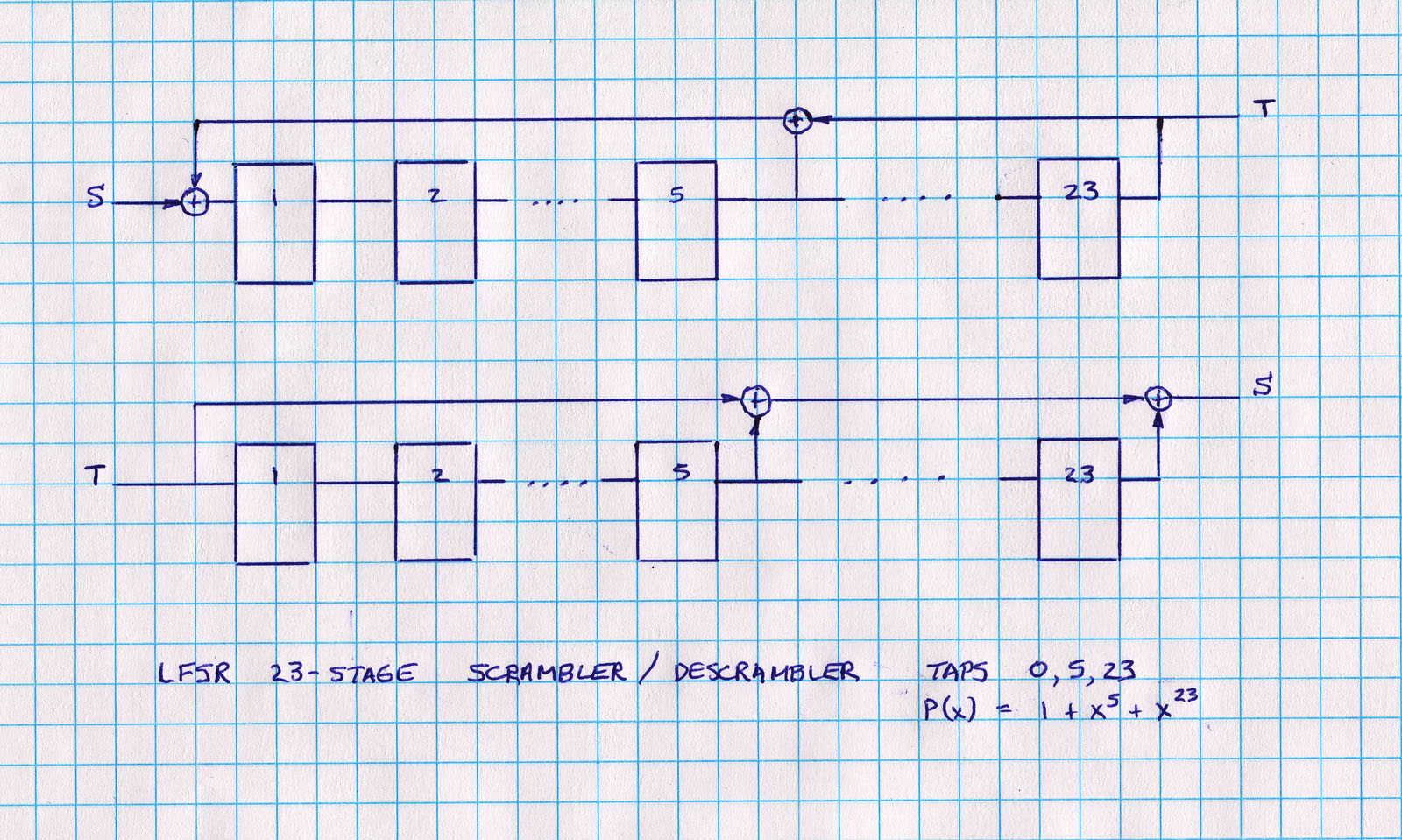
The pseudo-random sequence is generated by a linear feedback shift register (see diagram).  The serial data enters the LFSR, where each stage is a D-type flip-flop equivalent to one time unit of delay.  The delayed signal is tapped, with XOR (modulo-2) feedback with the input signal.  For the descrambler, the XOR process is feed-forward.

Linear feedback shift registers are often expressed in polynomial form.  The table below lists the polynomial representations of a number of LFSRs. Certain combinations of taps are preferred to give maximal sequence length (see table).


The previous diagram shows an n = 5 stage self-synchronizing scrambler/descrambler, implemented using LFSRs.  For an n-bit LFSR, these will resynchronize after n bits if the scrambler and descrambler become desynchronized due to bit errors. A slight disadvantage is that each bit error is multiplied by the number of taps used by the LFSR (typically 3).

Some input data sequences to the LFSR can result in undesirable side effects.  For instance, if the LFSR gets into an all-zero state, it will stay stuck in that state (so-called killer packet problem).  The problem can be minimized by using a longer LFSR (say n>23), or adding logic to detect and correct the all-zeros state.

For most input sequences, the output of the scrambler will appear to be a random sequence of 1s and 0s, with a 0.5 probablility of each.  That is, the output will be DC balanced.  In addition, the output sequence will have a high density of transitions which are essential for clock recovery.


The figure shows the 'impulse response' of feeding a logic 1, followed by zeros to a 23-stage scrambler. After an initial delay of 23 clock cycles, the output (TXD) is randomized while the input (SDATA) is all zeros.

In EPLD terms, the following is the representation of a 23-stage scrambler/descrambler codes using Altera megafunctions in verilog.  Note that the shift register numbering starts at 0, where the tap numbering for LFSRs normally starts at 1 (the reader can work out the correspondence).


线性移位寄存器LFSR电路


线性移位寄存器LFSR电路

space.gif
../../images/main/bullet_green_ball.gif
源自於http://www.asic-world.com/examples/verilog/lfsr.html
Random Counter (LFSR)

  1 //-----------------------------------------------------
  2 // Design Name : lfsr
  3 // File Name   : lfsr.v
  4 // Function    : Linear feedback shift register
  5 // Coder       : Deepak Kumar Tala
  6 //-----------------------------------------------------
  7 module lfsr    (
  8 out             ,  // Output of the counter
  9 enable          ,  // Enable  for counter
 10 clk             ,  // clock input
 11 reset              // reset input
 12 );
 13 
 14 //----------Output Ports--------------
 15 output [7:0] out;
 16 //------------Input Ports--------------
 17 input [7:0] data;
 18 input enable, clk, reset;
 19 //------------Internal Variables--------
 20 reg [7:0] out;
 21 wire        linear_feedback;
 22 
 23 //-------------Code Starts Here-------
 24 assign linear_feedback =  ! (out[7] ^ out[3]);
 25 
 26 always @(posedge clk)
 27 if (reset) begin // active high reset
 28   out <= 8'b0 ;
 29 end else if (enable) begin
 30   out <= {out[6],out[5],
 31           out[4],out[3],
 32           out[2],out[1],
 33           out[0], linear_feedback};
 34 end 
 35 
 36 endmodule // End Of Module counter
You could download file lfsr.v here
space.gif
../../images/main/bullet_green_ball.gifLFSR Up/Down
space.gif

  1 `define WIDTH 8 
  2 module lfsr_updown (
  3 clk       ,   // Clock input
  4 reset     ,   // Reset input
  5 enable    ,   // Enable input
  6 up_down   ,   // Up Down input
  7 count     ,   // Count output
  8 overflow      // Overflow output
  9 );
 10 
 11  input clk;
 12  input reset;
 13  input enable; 
 14  input up_down;
 15 
 16  output [`WIDTH-1 : 0] count;
 17  output overflow;
 18 
 19  reg [`WIDTH-1 : 0] count;
 20 
 21  assign overflow = (up_down) ? (count == {{`WIDTH-1{1'b0}}, 1'b1}) : 
 22                                (count == {1'b1, {`WIDTH-1{1'b0}}}) ;
 23 
 24  always @(posedge clk)
 25  if (reset) 
 26     count <= {`WIDTH{1'b0}};
 27  else if (enable) begin
 28     if (up_down) begin
 29       count <= {~(^(count & `WIDTH'b01100011)),count[`WIDTH-1:1]};
 30     end else begin
 31       count <= {count[`WIDTH-2:0],~(^(count &  `WIDTH'b10110001))};
 32     end
 33  end
 34 
 35 endmodule
You could download file lfsr_updown.v here
space.gif
space.gif

  1 module tb();
  2  reg clk;
  3  reg reset;
  4  reg enable;
  5  reg up_down;
  6 
  7  wire [`WIDTH-1 : 0] count;
  8  wire overflow;
  9 
 10 initial begin
 11   $monitor("rst %b en %b updown %b cnt %b overflow %b",
 12      reset,enable,up_down,count, overflow);
 13   clk = 0;
 14   reset = 1;
 15   enable = 0;
 16   up_down = 0;
 17    #10  reset = 0;
 18    #1  enable = 1;
 19    #20  up_down = 1;
 20    #30  $finish;
 21 end
 22 
 23 always  #1  clk = ~clk;
 24 
 25 lfsr_updown U(
 26 .clk      ( clk      ),
 27 .reset    ( reset    ),
 28 .enable   ( enable   ),
 29 .up_down  ( up_down  ),
 30 .count    ( count    ),
 31 .overflow ( overflow )
 32 );
 33 
 34 endmodule
You could download file lfsr_updown_tb.v here

上數與下數計數器 0->15 , 15->0

// 4bits上數與下數計數器 適用於DE2-70 

4bits Binary Up-Down Counter

On this page, I will introduce "4 bits Binary Up-Down Counter" which was written in VHDL.
This source file is written for CPLD(XC9536-PC44).
The other CPLD device can be used if arranging a little.

The logic is the function which is same as Logic IC( 74161 ) approximately.
But, a carry bit, a borrow bit aren't supported.
Those functions can be put if you arrange logic.

I programed this logic in CPLD and confirmed in the operation and had confirmed normal operation. 
 Source code and Explanation

 Fitting report

 Processing parameter specification

Operating state table
InputOutputOperation
CLEARLOADCEUPCLKQ3,Q2,Q1,Q0
HXXXX0,0,0,0Counter clear
LHXXD3,D2,D1,D0Counter preset
LLLXQ = QCount stop
LLHHQ = Q+1Count up
LLHLQ = Q-1Count down

H : High level
L : Low level
X : Don't care
CLK is effective when changing into H from the L.


// Ch08 cnt1.v
// 上數與下數計數器

module cnt1 (SW, LEDR, LEDG , CLOCK_50,CLOCK_27 ,KEY 
             ,HEX0 ,HEX1 ,HEX2,HEX3 ,HEX4 );

input  [17:0] SW; // toggle switches
input  [3:0] KEY;     // Push bottom
input  CLOCK_27; //Clock 27MHz 
input  CLOCK_50; //Clock 50MHz

output [17:0] LEDR; // red  LEDS   
  output [7:0] LEDG; // green LEDs
    
    output [6:0] HEX0,HEX1,HEX2,HEX3 ,HEX4; //7-segment display

//set original program input , output 

//(Clk,Clr,Q1,Q2);
//input  Clk,Clr; // 一位元輸入
//output [3:0] Q1,Q2; // 四位元輸出 
//reg    [3:0] Q1,Q2; // 宣告為暫存器資料

reg  [3:0] Q1,Q2; // 宣告為暫存器資料
wire HZ_1;  //1HZ Clock
    wire Clr;
    
    wire [7:0] segout0;   //HEX 0
    wire [7:0] segout1;   //HEX 1
    
  
    assign Clr=KEY[0];
     
    
  //module _1HZ (CLK, RSTn, LED_Out);

_1HZ UUT01
     (.CLK(CLOCK_50),
    .RSTn(Clr),
    .LED_Out(HZ_1));


// 上緣觸發時脈, 上緣同步清除, 上數計數器
always@ (posedge HZ_1 or negedge Clr ) 
begin
if (!Clr)  Q1 = 0;
else   Q1 = Q1 + 1;

end
// 上緣觸發時脈, 上緣同步清除, 下數計數器
always@ (negedge HZ_1 or negedge Clr )
begin
if (!Clr) Q2 = 15;
else  Q2 = Q2 - 1;
    end


_7seg UUT0(.hex(Q1),
               .seg(segout0));
    
    _7seg UUT1(.hex(Q2),
               .seg(segout1));           
                      
    assign HEX0=segout0[6:0];
    
    assign HEX1=segout1[6:0];

assign LEDG[3:0]=Q1;
assign LEDR[3:0]=Q2;

endmodule

/*
// Ch08 cnt1.v
// 上數與下數計數器

module cnt1 (Clk,Clr,Q1,Q2);
input  Clk,Clr; // 一位元輸入
output [3:0] Q1,Q2; // 四位元輸出 
reg    [3:0] Q1,Q2; // 宣告為暫存器資料

// 上緣觸發時脈, 上緣同步清除, 上數計數器
always@ (posedge Clk) 
  if (Clr)  Q1 = 0;
  else    Q1 = Q1 + 1;

// 上緣觸發時脈, 上緣同步清除, 減二下數計數器
always@ (posedge Clk) 
  if (Clr)  Q2 = 15;
  else    Q2 = Q2 - 2;

endmodule
*/


//-----------------------------------------
//Common-cathod seven segment display
//using case.....endcase statement
//Filename : sevenseg_case.v
//----------------------------------------- 
module _7seg(hex , seg);

    input  [3:0] hex;
    output [7:0] seg;
    reg    [7:0] seg;


// segment encoding
//      0
//     ---  
//  5 |   | 1
//     ---   <- 6
//  4 |   | 2
//     ---
//      3

always @(hex)
begin
case (hex)
       // Dot point is always disable
       4'b0001 : seg = 8'b11111001;   //1 = F9H
       4'b0010 : seg = 8'b10100100;   //2 = A4H
       4'b0011 : seg = 8'b10110000;   //3 = B0H
       4'b0100 : seg = 8'b10011001;   //4 = 99H
       4'b0101 : seg = 8'b10010010;   //5 = 92H
       4'b0110 : seg = 8'b10000010;   //6 = 82H
       4'b0111 : seg = 8'b11111000;   //7 = F8H
       4'b1000 : seg = 8'b10000000;   //8 = 80H
       4'b1001 : seg = 8'b10010000;   //9 = 90H
       4'b1010 : seg = 8'b10001000;   //A = 88H
       4'b1011 : seg = 8'b10000011;   //b = 83H
       4'b1100 : seg = 8'b11000110;   //C = C6H
       4'b1101 : seg = 8'b10100001;   //d = A1H
       4'b1110 : seg = 8'b10000110;   //E = 86H
       4'b1111 : seg = 8'b10001110;   //F = 8EH
       default : seg = 8'b11000000;   //0 = C0H
     endcase
   end
   

endmodule


//====================================
//Clock input 50MHZ
//====================================
 module _1HZ (CLK, RSTn, LED_Out);

    input CLK;
    input RSTn;
    output LED_Out;
    
    /*************************************/
    
    parameter T1S = 24'd50_000_000;  //50MHZ 
    
    /*************************************/
    
    reg [23:0]Count1;
    
    always @ ( posedge CLK or negedge RSTn )
    begin
     if( !RSTn ) 
         Count1 <= 24'd0;
     else if( Count1 == T1S )
         Count1 <= 24'd0;
     else
         Count1 <= Count1 + 1'b1;
end        
 /*************************************/
reg rLED_Out;
 always @ ( posedge CLK or negedge RSTn )
    begin
        if( !RSTn ) 
            rLED_Out <= 1'b0;
        else if( Count1 >= 24'd0 && Count1 < 24'd25_000_000 )
          //0.5sec ON , o.5sec OFF
            rLED_Out <= 1'b1;
        else 
            rLED_Out <= 1'b0;
     end  
          
     /***************************************/
     
     assign LED_Out = rLED_Out;
     
     /***************************************/
              
    
endmodule


2012年11月2日 星期五

七段顯示器的霹靂燈 適用於DE2-70

七段顯示器的霹靂燈 適用於DE2-70
a->b->c->d->e->f->e->d->c->b->a->b....................


// Ch08 pili_1.v
// 七段顯示霹靂燈

module pili_ex1(SW, LEDR, LEDG , CLOCK_50 , 
               CLOCK_27 ,KEY ,HEX0 ,HEX1 ,
               HEX2,HEX3 ,HEX4,HEX5 ,HEX6,HEX7 );

input  [17:0] SW; // toggle switches
input  [3:0] KEY;     // Push bottom
input  CLOCK_27; //Clock 27MHz 
input  CLOCK_50; //Clock 50Mhz


output [17:0] LEDR; // red  LEDS   
output [7:0]  LEDG; // green LEDs
    
    output [6:0] HEX0,HEX1,HEX2,HEX3,HEX4,HEX5,HEX6 ,HEX7; //7-segment display

//set original program input , output 

wire   sys_clk;
wire   rst_n;
    reg [3:0] L;
    wire HZ_1;  //1HZ Clock
    reg    [7:0] seg;


//assign to DE2-70 hardware     
  
    assign sys_clk = CLOCK_50;
    assign rst_n = KEY[0];
    
    // reg A,B,C,D,E,F;
      
  //module _1HZ (CLK, RSTn, LED_Out);

_1HZ UUT01
     (.CLK(sys_clk),
    .RSTn(rst_n),
    .LED_Out(HZ_1));


  always @(posedge HZ_1 or negedge rst_n ) 
begin
        begin
if(!rst_n) 
L[3:0]=0;

    else if (L>=4'b1100)
L[3:0]=4'b1;

else 
L=L+1'b1;
   
   end
   
    
   case (L)

// Dot point is always disable
4'b0001 : seg = 8'b1111_1110;   //1 = a
4'b0010 : seg = 8'b1111_1101;   //2 = b
4'b0011 : seg = 8'b1111_1011;   //3 = c
4'b0100 : seg = 8'b1111_0111;   //4 = d
4'b0101 : seg = 8'b1110_1111;   //5 = e
4'b0110 : seg = 8'b1101_1111;   //6 = f
4'b0111 : seg = 8'b1111_1110;   //7 = a
4'b1000 : seg = 8'b1101_1111;   //8 = f
4'b1001 : seg = 8'b1110_1111;   //9 = e
4'b1010 : seg = 8'b1111_0111;   //A = d
4'b1011 : seg = 8'b1111_1011;   //B = c
4'b1100 : seg = 8'b1111_1101;   //C = b

default : seg = 8'b11111111;   //OFF

endcase
    end
   
// assign {A,B,C,D,E,F} = L[6:1];

assign HEX0=seg[6:0];
assign HEX1=seg[6:0];
assign HEX2=seg[6:0];
assign HEX3=seg[6:0];
assign HEX4=seg[6:0];
assign HEX5=seg[6:0];
assign HEX6=seg[6:0];
assign HEX7=seg[6:0];

assign LEDG[5:0]=seg[5:0];


endmodule


/*
module pili_1 
(Clk,Clr,A,B,C,D,E,F);
input  Clk,Clr; // 一位元輸入
output A,B,C,D,E,F; // 一位元輸出
reg    [6:0] L; // 宣告為暫存器資料

// 上緣觸發時脈, 上緣同步清除
always@ (posedge Clk) 
  if (Clr) L = 7'b1000000;  // A, 順時針
  else if (L == 7'b1000000) L = 7'b0100000;  // B, 順時針
  else if (L == 7'b0100000) L = 7'b0010000;  // C, 順時針
  else if (L == 7'b0010000) L = 7'b0001000;  // D, 順時針
  else if (L == 7'b0001000) L = 7'b0000100;  // E, 順時針
  else if (L == 7'b0000100) L = 7'b0000010;  // F, 順時針
  else if (L == 7'b0000010) L = 7'b1000001;  // A, 逆時針
  else if (L == 7'b1000001) L = 7'b0000011;  // F, 逆時針
  else if (L == 7'b0000011) L = 7'b0000101;  // E, 逆時針
  else if (L == 7'b0000101) L = 7'b0001001;  // D, 逆時針
  else if (L == 7'b0001001) L = 7'b0010001;  // C, 逆時針
  else if (L == 7'b0010001) L = 7'b0100001;  // B, 逆時針
  else if (L == 7'b0100001) L = 7'b1000000;  // A, 順時針
  else                 L = 7'b0000000;  // 不顯示
assign {A,B,C,D,E,F} = L[6:1];

endmodule
*/


//====================================
//Clock input 50MHZ
//====================================
 module _1HZ (CLK, RSTn, LED_Out);

    input CLK;
    input RSTn;
    output LED_Out;
    
    /*************************************/
    
    parameter T1S = 24'd50_000_000;  //50MHZ 
    
    /*************************************/
    
    reg [23:0]Count1;
    
    always @ ( posedge CLK or negedge RSTn )
    begin
     if( !RSTn ) 
         Count1 <= 24'd0;
     else if( Count1 == T1S )
         Count1 <= 24'd0;
     else
         Count1 <= Count1 + 1'b1;
end        
 /*************************************/

reg rLED_Out;


 always @ ( posedge CLK or negedge RSTn )
    begin
        if( !RSTn ) 
            rLED_Out <= 1'b0;
        else if( Count1 >= 24'd0 && Count1 < 24'd25_000_000 )
          //0.5sec ON , o.5sec OFF
            rLED_Out <= 1'b1;
        else 
            rLED_Out <= 1'b0;
     end  
          
     /***************************************/
     
     assign LED_Out = rLED_Out;
     
     /***************************************/
              
    
endmodule

環形計數器---Ring Counter 適用於DE2-70


環形計數器---Ring Counter 適用於DE2-70
==========================================
設計方法


1.每一正反器波形皆相同,只是相位不同。
2.每個正反器輸出責任週期皆為25%。
3.每個正反器輸出信號週期皆為輸入CK的4倍。
==========================================
形式1: 1000->0100->0010->0001->1000->.....


形式2: 
1000->1100->1110->1111->0111->0011->0001->0000
->1000->>.................

// Ch08 cnt5.v
// 環形計數器

module cnt5 (SW, LEDR, LEDG , CLOCK_27 ,KEY ,HEX0 ,HEX1 ,HEX2,HEX3 ,HEX4 );

input  [17:0] SW; // toggle switches
input  [3:0] KEY;     // Push bottom
input  CLOCK_27; //Clock 27MHz , 50Mhz
output [17:0] LEDR; // red  LEDS   
  output [8:0] LEDG; // green LEDs
    
    output [6:0] HEX0,HEX1,HEX2,HEX3 ,HEX4; //7-segment display

//set original program input , output 


//cnt5 (Clk,Clr,Q1,Q2);
//input  Clk,Clr; // 一位元輸入
//output [3:0]  Q1,Q2; // 四位元輸出
//reg    [3:0]  Q1,Q2; // 宣告為暫存器資料
wire   Clk ,Clr ;
reg    [3:0]  Q1=4'b1000;
reg    [3:0]  Q2=4'b1000; // 宣告為暫存器資料
wire [7:0] segout0;   //HEX 0
wire [7:0] segout1;   //HEX 1
assign Clk=KEY[0];
assign Clr=KEY[1];

// 產生計數值
always@ (negedge Clk or negedge Clr)
  if (!Clr)
    begin
      Q1 = 4'b1000; // Q1 初值
      Q2 = 4'b1000; // Q2 初值
    end
  else
    begin
      Q1 = { Q1[0],Q1[3:1]}; // 循環右移位
      Q2 = {~Q2[0],Q2[3:1]}; // 循環右移位(反相)
   end 

  
_7seg UUT0(.hex(Q1),
               .seg(segout0));
               
_7seg UUT1(.hex(Q2),
               .seg(segout1));
               
    assign HEX0=segout0[6:0];
    assign HEX1=segout1[6:0];
    
    assign LEDG[7:4]=Q1;
    assign LEDR[3:0]=Q2;


endmodule


//-----------------------------------------
//Common-cathod seven segment display
//using case.....endcase statement
//Filename : sevenseg_case.v
//----------------------------------------- 
module _7seg(hex , seg);
    input  [3:0] hex;
    output [7:0] seg;
    reg    [7:0] seg;


// segment encoding
//      0
//     ---  
//  5 |   | 1
//     ---   <- 6
//  4 |   | 2
//     ---
//      3
always @(hex)
begin
case (hex)
       // Dot point is always disable
       4'b0001 : seg = 8'b11111001;   //1 = F9H
       4'b0010 : seg = 8'b10100100;   //2 = A4H
       4'b0011 : seg = 8'b10110000;   //3 = B0H
       4'b0100 : seg = 8'b10011001;   //4 = 99H
       4'b0101 : seg = 8'b10010010;   //5 = 92H
       4'b0110 : seg = 8'b10000010;   //6 = 82H
       4'b0111 : seg = 8'b11111000;   //7 = F8H
       4'b1000 : seg = 8'b10000000;   //8 = 80H
       4'b1001 : seg = 8'b10010000;   //9 = 90H
       4'b1010 : seg = 8'b10001000;   //A = 88H
       4'b1011 : seg = 8'b10000011;   //b = 83H
       4'b1100 : seg = 8'b11000110;   //C = C6H
       4'b1101 : seg = 8'b10100001;   //d = A1H
       4'b1110 : seg = 8'b10000110;   //E = 86H
       4'b1111 : seg = 8'b10001110;   //F = 8EH
       default : seg = 8'b11000000;   //0 = C0H
     endcase
   end
   
endmodule


  清除項目編譯快取 執行 flutter clean 重新取得套件依賴 執行 flutter pub get 完整重新編譯並執行 flutter run 1. 新增專案套件 (pubspec.yaml) 在 Flutter 專案根目錄下的 pubspec.yaml 中,新增 ...