2020年5月31日 星期日

安裝Node-RED

安裝Node-RED

以Windows安裝Node-RED

1.先到Node.js官網下載LTS版
https://ithelp.ithome.com.tw/upload/images/20181016/20112219KY7P4ULJ6A.png
2.執行後一路下一步
https://ithelp.ithome.com.tw/upload/images/20181016/20112219NdAuwQwW0N.png
3.確認Node.Js與NPM版本
https://ithelp.ithome.com.tw/upload/images/20181016/20112219CZJhCnvDEn.png
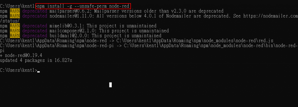
4.輸入 npm install -g --unsafe-perm node-red 安裝Node-RED
https://ithelp.ithome.com.tw/upload/images/20181016/20112219R2UY4wxHiB.png
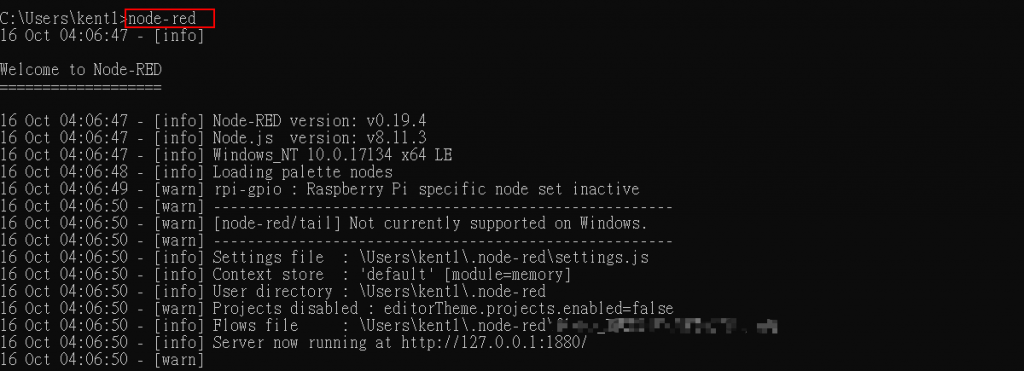
5.輸入node-red啟動Node-RED
https://ithelp.ithome.com.tw/upload/images/20181016/20112219qYt2zzQqBS.png
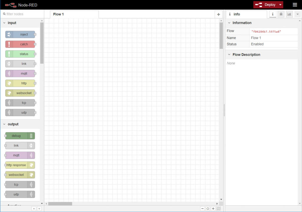
6.啟動瀏覽器 輸入127.0.0.1:1880
https://ithelp.ithome.com.tw/upload/images/20181016/20112219PvSQ9Mus5k.png
即可使用Node-RED

2020年5月26日 星期二

Binary to BCD Converter

Binary to BCD Converter

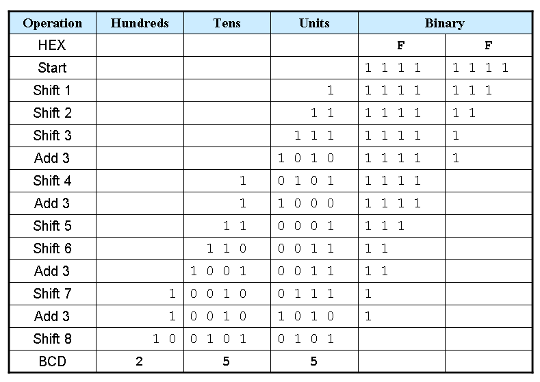
Shift and Add-3 Algorithm


  1. Shift the binary number left one bit.
  2. If 8 shifts have taken place, the BCD number is in the HundredsTens, and Units column.
  3. If the binary value in any of the BCD columns is 5 or greater, add 3 to that value in that BCD column.
  4. Go to 1.
OperationHundredsTensUnitsBinary
HEX


FF
Start


1 1 1 11 1 1 1

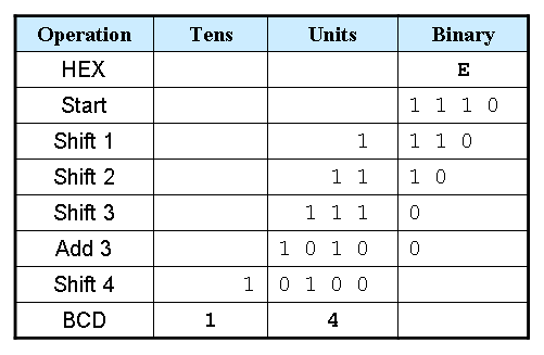
Example 1: Convert hex E to BCD


Example 2: Convert hex FF to BCD


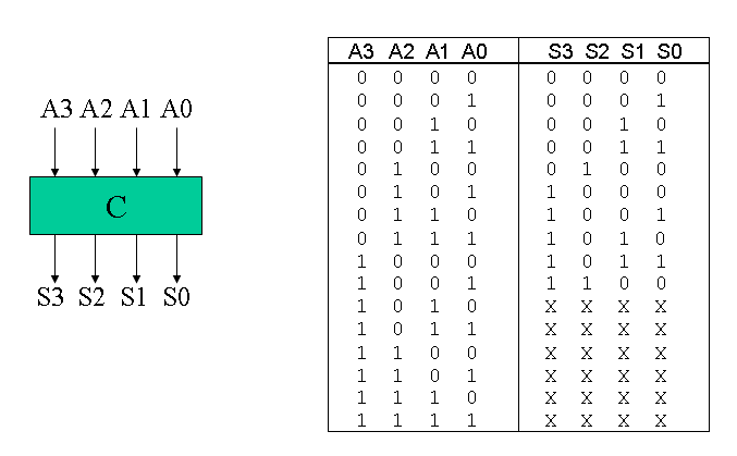
Truth table for Add-3 Module


Here is a Verilog module for this truth table.
module add3(in,out);
input [3:0] in;
output [3:0] out;
reg [3:0] out;

always @ (in)
 case (in)
 4'b0000: out <= 4'b0000;
 4'b0001: out <= 4'b0001;
 4'b0010: out <= 4'b0010;
 4'b0011: out <= 4'b0011;
 4'b0100: out <= 4'b0100;
 4'b0101: out <= 4'b1000;
 4'b0110: out <= 4'b1001;
 4'b0111: out <= 4'b1010;
 4'b1000: out <= 4'b1011;
 4'b1001: out <= 4'b1100;
 default: out <= 4'b0000;
 endcase
endmodule

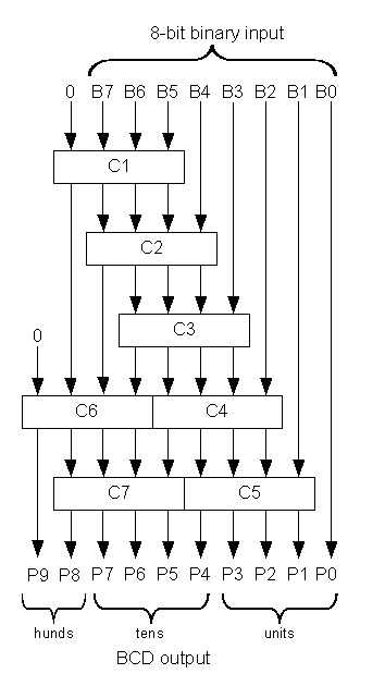
Binary-to-BCD Converter Module


Here is a structural Verilog module corresponding to the logic diagram.
module binary_to_BCD(A,ONES,TENS,HUNDREDS);
input [7:0] A;
output [3:0] ONES, TENS;
output [1:0] HUNDREDS;
wire [3:0] c1,c2,c3,c4,c5,c6,c7;
wire [3:0] d1,d2,d3,d4,d5,d6,d7;

assign d1 = {1'b0,A[7:5]};
assign d2 = {c1[2:0],A[4]};
assign d3 = {c2[2:0],A[3]};
assign d4 = {c3[2:0],A[2]};
assign d5 = {c4[2:0],A[1]};
assign d6 = {1'b0,c1[3],c2[3],c3[3]};
assign d7 = {c6[2:0],c4[3]};
add3 m1(d1,c1);
add3 m2(d2,c2);
add3 m3(d3,c3);
add3 m4(d4,c4);
add3 m5(d5,c5);
add3 m6(d6,c6);
add3 m7(d7,c7);
assign ONES = {c5[2:0],A[0]};
assign TENS = {c7[2:0],c5[3]};
assign HUNDREDS = {c6[3],c7[3]};

endmodule

General Binary-to-BCD Converter

The linked code is a general binary-to-BCD Verilog module, but I have not personally tested the code.

2020年5月24日 星期日

DE2-115 0000-9999 Counter 十進制計數器

DE2-115 0000-9999 Counter 十進制計數器


module cnt_9999 (
  input  CLOCK_50, // 50 MHz clock
  input  [3:0] KEY,      // Pushbutton[3:0]
  input  [17:0] SW, // Toggle Switch[17:0]
  output [6:0] HEX0,HEX1,HEX2,HEX3,HEX4,HEX5,HEX6,HEX7,  // Seven Segment Digits
  output [8:0] LEDG,  // LED Green
  output [17:0] LEDR   // LED Red
 );
 // blank unused 7-segment digits
//assign HEX0 = 7'b111_1111;
//assign HEX1 = 7'b111_1111;
//assign HEX2 = 7'b111_1111;
//assign HEX3 = 7'b111_1111;
assign HEX4 = 7'b111_1111;
assign HEX5 = 7'b111_1111;
assign HEX6 = 7'b111_1111;
assign HEX7 = 7'b111_1111;

assign LEDR=SW;
// Setup clock divider
wire [6:0] myclock;

wire [3:0]cnt_1s,cnt_10s,cnt_100s,cnt_1000s;
wire tens_en,huns_en,thou_en,thous_10k_en;
wire tc_1s,tc_10s,tc_100s,tc_1000s;
/*
 divide_by_50 d6(clk_1Mhz,CLK,RST);
 divide_by_10 d5(clk_100Khz,clk_1Mhz,RST);
 divide_by_10 d4(clk_10Khz,clk_100Khz,RST);
 divide_by_10 d3(clk_1Khz,clk_10Khz,RST);
 divide_by_10 d2(clk_100hz,clk_1Khz,RST);
 divide_by_10 d1(clk_10hz,clk_100hz,RST);
 divide_by_10 d0(clk_1hz,clk_10hz,RST);
*/
 clock_divider cdiv(CLOCK_50,KEY[0],myclock);
 //module clock_divider(CLK,RST,clock);
 cnt_10 u0(SW[0],myclock[1],KEY[0],cnt_1s,tc_1s);
 //module cnt_10(ce,clk,clr,Q,tc)
 cnt_10 u10(tens_en,myclock[1],KEY[0],cnt_10s,tc_10s);
 cnt_10 u100(huns_en,myclock[1],KEY[0],cnt_100s,tc_100s);
 cnt_10 u1000(thou_en,myclock[1],KEY[0],cnt_1000s,tc_1000s);

 assign tens_en = tc_1s   & SW[0];
 assign huns_en = tc_10s  & tens_en ;
 assign thou_en = tc_100s & huns_en;


  _7seg(cnt_1s , HEX0);
  _7seg(cnt_10s , HEX1);
  _7seg(cnt_100s , HEX2);  
  _7seg(cnt_1000s , HEX3);


endmodule

module clock_divider(CLK,RST,clock);
 input CLK,RST;
 output [6:0] clock;
 wire clk_1Mhz,clk_100Khz,clk_10Khz,clk_1Khz,clk_100hz,clk_10hz,clk_1hz;

 assign clock = {clk_1Mhz,clk_100Khz,clk_10Khz,clk_1Khz,clk_100hz,clk_10hz,clk_1hz};

 divide_by_50 d6(clk_1Mhz,CLK,RST);
 divide_by_10 d5(clk_100Khz,clk_1Mhz,RST);
 divide_by_10 d4(clk_10Khz,clk_100Khz,RST);
 divide_by_10 d3(clk_1Khz,clk_10Khz,RST);
 divide_by_10 d2(clk_100hz,clk_1Khz,RST);
 divide_by_10 d1(clk_10hz,clk_100hz,RST);
 divide_by_10 d0(clk_1hz,clk_10hz,RST);
endmodule


module divide_by_10(Q,CLK,RST);
input CLK, RST;
output Q;
reg Q;
reg [2:0] count;
always @ (posedge CLK or negedge RST)
 begin
  if (~RST)
   begin
    Q <= 1'b0;
    count <= 3'b000;
   end
  else if (count < 4)
   begin 
     count <= count+1'b1;
   end
  else 
   begin
    count <= 3'b000;
    Q <= ~Q;
   end
 end
endmodule

module divide_by_50(Q,CLK,RST);
input CLK, RST;
output Q;
reg Q;
reg [4:0] count;
always @ (posedge CLK or negedge RST)
 begin
  if (~RST)
   begin
    Q <= 1'b0;
    count <= 5'b00000;
   end
  else if (count < 24)
   begin 
     count <= count+1'b1;
   end
  else 
   begin
    count <= 5'b00000;
    Q <= ~Q;
   end
 end
endmodule

module cnt_10(ce,clk,clr,Q,tc);

input ce,clk,clr;
output [3:0]Q;
output tc;

reg [3:0]count;

always@(posedge clk or negedge clr)
begin
if (!clr)
count<=4'h0;
else 
if (ce) 
if (count==4'h9)
count<=4'h0;
else
count<=count+1;
end
assign Q=count;
assign tc= (count==4'h9);

endmodule
//-----------------------------------------
//Common-cathod seven segment display
//using case.....endcase statement
//Filename : sevenseg_case.v
//----------------------------------------- 
module _7seg(hex , seg);
    input  [3:0] hex;
    output [7:0] seg;
    reg    [7:0] seg;
 
 // segment encoding
 //      0
 //     ---  
 //  5 |   | 1
 //     ---   <- 6
 //  4 |   | 2
 //     ---
 //      3
 always @(hex)
 begin
  case (hex)
       // Dot point is always disable
       4'b0001 : seg = 8'b11111001;   //1 = F9H
       4'b0010 : seg = 8'b10100100;   //2 = A4H
       4'b0011 : seg = 8'b10110000;   //3 = B0H
       4'b0100 : seg = 8'b10011001;   //4 = 99H
       4'b0101 : seg = 8'b10010010;   //5 = 92H
       4'b0110 : seg = 8'b10000010;   //6 = 82H
       4'b0111 : seg = 8'b11111000;   //7 = F8H
       4'b1000 : seg = 8'b10000000;   //8 = 80H
       4'b1001 : seg = 8'b10010000;   //9 = 90H
       4'b1010 : seg = 8'b10001000;   //A = 88H
       4'b1011 : seg = 8'b10000011;   //b = 83H
       4'b1100 : seg = 8'b11000110;   //C = C6H
       4'b1101 : seg = 8'b10100001;   //d = A1H
       4'b1110 : seg = 8'b10000110;   //E = 86H
       4'b1111 : seg = 8'b10001110;   //F = 8EH
       default : seg = 8'b11000000;   //0 = C0H
     endcase
   end
   
endmodule


2020年5月22日 星期五

Simple Solver 真值表轉布林代數

Simple Solver 真值表轉布林代數


Simple Solver

Links & Version Info
Download Links
Version 5.5
A Simple Solver free software download includes the application, help files, and dozens of examples.
New Simple Solver versions will be issued promptly to correct any reported bugs, or to provide user-suggested improvements or additional features.
Version 5.5 changes:
- fix minor bug
- All tools: update Help files
DOWNLOAD Simple Solver from SimpleSolverLogic.com
- Verified by Norton 360 & Malwarebytes
CAUTION - All Simple Solver windows must be closed before installing an update
Simple Solver is also available at FreewareFiles
100% Clean - Tested by FreewareFiles.com
And many other reliable sites including:
Softpedia     BestFreeware     BestSoftware     Download.com    

Flip-Flop D , T , JK

Flip-Flop D , T , JK , RS 

module D_FF(D,clk,sync_reset,Q);
input D; // Data input 
input clk; // clock input 
input sync_reset; // synchronous reset 
output reg Q; // output Q 
always @(posedge clk) 
begin
 if(sync_reset==1'b1)
  Q <= 1'b0; 
 else 
  Q <= D; 
end 
endmodule 


`timescale 100ns/1ns
module TB;
reg D,clk,sync_reset;
wire Q;

D_FF UUT(D,clk,sync_reset,Q);

initial begin
  clk=0;
     forever #5 clk = ~clk;  
end 

initial begin
D=0; sync_reset=0;
#10 sync_reset=1;
#10 sync_reset=0;
#12 D=1;
#12 D=0;
#12 D=1;
#10 sync_reset=1;
#12 D=1;
#10 $stop;
end
endmodule


module T(T,clk,sync_reset,Q); // T Flip Flop
input T; // Data input 
input clk; // clock input 
input sync_reset; // synchronous reset 
output reg Q; // output Q 

always @(posedge clk) 
begin
 if(sync_reset==1'b1)

  Q <= 1'b0; 
 else 
 if (T)
          Q <= ~Q;
      else
          Q <= Q;
end 
endmodule 

`timescale 100ns/1ns
module TB;
reg T,clk,sync_reset;
wire Q;

T UUT(T,clk,sync_reset,Q);

initial begin
  clk=0;
     forever #5 clk = ~clk;  
end 

initial begin
T=0; sync_reset=0;
#10 sync_reset=1;
#10 sync_reset=0;
#12 T=1;
#12 T=0;
#18 T=1;
#10 sync_reset=1;
#25 T=1;
#10 $stop;
end
endmodule

module JK_FF (J,K,clk,sync_reset,Q);
 input J,K,clk,sync_reset;
 output reg Q;
  
 always @ (posedge clk) begin
if (sync_reset==1'b1)
Q <= 1'b0; 
else
      case ({J,K})
         2'b00 :  Q <= Q;
         2'b01 :  Q <= 0;
         2'b10 :  Q <= 1;
         2'b11 :  Q <= ~Q;
      endcase
end

endmodule

`timescale 100ns/1ns
module TB;
reg J,K,clk,sync_reset;
wire Q;

JK_FF UUT (J,K,clk,sync_reset,Q);

initial begin
  clk=0;
     forever #5 clk = ~clk;  
end 

initial begin
J=1;K=0; sync_reset=0;
#10 sync_reset=1;
#10 sync_reset=0;
#12 J=1;K=0;
#12 J=1;K=1;
#12 J=0;K=1;
#10 sync_reset=1;
#12 J=1;K=1;
#10 sync_reset=0;
#12 J=0;K=1;
#12 J=1;K=0;
#10 $stop;

end

endmodule


Digital System Design using FPGA

Digital System Design using FPGA

https://esrd2014.blogspot.com/

Combinatorial Circuit Design

Full Adder
4 bit Carry Ripple Adder
8 bit Magnitude Comparator
8-to-1 Multiplexer
3-to-8 Decoder
Barrel Shifter
ALU

Sequential Circuit Design

2020年5月21日 星期四

Sequential Verilog

Sequential Verilog

Al Wood

Registers

A simple memory to hold state, normally implemented as D-type flip-flop.
reg  y;
reg [1:0] a2, b2;
Inputs and outputs can be declared as registers:
module mymod (
   input reg [1:0] y2;
   output reg [2:0] y3;
By convention usually only outputs are registers and inputs are wires.

Example: Decoder with register

module decoder (
   input  [1:0]     a,
   input            en,
   output reg [3:0] y
  )

   always_comb
      casex ({en,a})
         3'b0xx: y = 4'b0000;
         3'b100: y = 4'b0001;
         3'b101: y = 4'b0010;
         3'b110: y = 4'b0100;
         3'b111: y = 4'b1000;
      endcase    // {en,a}

endmodule

Sequential always blocks

always @(posedge clk)
   a <= b;
At the next positive edge of the clock, register a will acquire the value held in b (which could be a register or wire).
SystemVerilog provides:
always_ff @(posedge clk)
   a <= b;

Delayed (non-blocking) assignments

<= causes the value to be transferred on the next clock edge. It should only be used in sequential always blocks.
Conversely = (aka blocking assignment) happens immediately and should only be used in combinatorial always blocks.
This means you can do surprising things with registers:
always_ff @(posedge clk)
   begin
      a <= b;
      b <= a;
   end

Common problems

You now know Verilog :-) Here are the common “gotchas”.
  • Variable assigned in multiple always blocks
  • Incomplete branch or output assignment
always_comb
   if (a > b)
      gt = 1'b1; // no eq assignment in branch
   else if (a == b)
      eq = 1'b1; // no gt assignment in branch
  // final else branch omitted
According to Verilog definition gt and eq keep their previous values when not assigned which implies internal state, unintended latches are inferred.

Fixing incomplete output assignment (1)

These sort of issues cause endless hair pulling avoid such things. Here is how we could correct this:
always_comb
   if (a > b) begin
      gt = 1'b1;
      eq = 1'b0;
   end
   else if (a == b) begin
      gt = 1'b0;
      eq = 1'b1;
   end
   else begin
      gt = 1'b0;
      eq = 1'b0;
   end

Fixing incomplete output assignment (2)

Or we can use default values.
always_comb
   begin
      gt = 1'b0;
      eq = 1'b0;
      if (a > b)
         gt = 1'b1;
      else if (a==b)
         eq = 1'b1;
   end

Incomplete output with case statements (1)

Similar problems can occur with case statements:
always_comb
   case (a)
      2'b00: y = 1'b1;
      2'b10: y = 1'b0;
      2'b11: y = 1'b1;
   endcase

Incomplete output with case statements (2)

A default clause is a good catchall.
always_comb
   case (a)
      2'b00:    y =1'b1;
      2'b10:    y =1'b0;
      2'b11:    y =1'b1;
      default : y = 1'b1;
   endcase

Exercise 4

Which is actually lots of exercises, all in basic_verilog
  • blink: Make the LED flash. Extend to make LED’s flash in a pattern.
  • fibonacci: Count through the LEDs in a fibonacci sequence.
  • button: Make the LED’s count when you press the button. Why won’t it count nice and smoothly?
  • button_edge_detect: This solves the problem of detecting a button press.
  • lock: Unlock the device with a password. This leads into the next talk.

An Introduction to FPGA Programming

Learning materials and workshop notes


The materials and supporting workshop notes were originally developed for the first ever ChipHack event and have been updated since.
All the source materials can be found on the GitHub chiphack repository and wiki.
Note that these are under development, so may not be entirely suitable for unsupported use.
Some of the slide decks are prepared using Hieroglyph, and can be viewed directly on this website as either HTML pages or slides. Others are provided as plain PDF.
  • MyStorm Setup: htmlslides.
  • Basic Verilog: htmlslides.
  • Combinatorial Verilog: htmlslides.
  • Sequential Verilog: htmlslides.
  • UART design htmlslides.
  • Martin Campbell-Kelly on the history of EDSAC: part 1 PDF.
  • Martin Campbell-Kelly on the history of EDSAC: part 2 PDF.
  • Bill Purvis's EDSAC in Verilog PDF.
  • Recreating EDSAC peripherals htmlslides.
  • Hatim Kanchwala's EDSAC design htmlslides.
  • Kevin Murrell on the EDSAC replica project PDF.

Combinatorial Verilog

Combinatorial Verilog

Al Wood

Wires and net declarations

wire a, b;
wire y;
wire [1:0] a2, b2;
Inputs and outputs to and from modules are automatically declared as wires, unless they are subsequently declared as registers (next talk).
module mymod (
   input  [1:0] y2;
   output [2:0] y3;
  )

Logic bitwise primitives

Negation
assign y = ~a;
AND, OR and exclusive-OR gates
assign y = a & b;
assign y = a | b;
assign y = a ^ b;

Reduction

wire y;
wire [1:0] a2;
assign y = | a2;
is equivalent to:
wire y;
wire [1:0] a2;
assign y = a2[1] | a2[0];

Concatenation and Replication

wire y;
wire [1:0] y2;
wire [2:0] y3;

assign y2 = {a,b};            // creates a 2-bit signal of a with b
assign y2 = {a,1'b0};         // a with 1 bit binary 0 (constant)
assign y3 = {a,b,1'b1};       // a with b with binary 1 (constant)
assign y3 = {a,2'b10};        // a with 2 binary bits 1, 0
assign y3 = {a,a2};           // a with a2 (a2 is 2 bits)
assign y3 = {a,a2[0],1'b1};   // a with single bit from a2 with 1
assign {y2,y} = {y3[1:0],a};  // multiple assignment: creates y2 as
                              // 2 bits from y3 and y as a
assign y3 = {a,2{1'b1}};      // a with 2 lots of binary 1
Note use of // to introduce a comment.

Shifting

Both arithmetic and logic shifts are provided. The following table illustrates the difference.
a           a >> 2      a >>> 2     a << 2      a <<< 3
01001111    00010011    00010011    00111100    00111100
11001111    00110011    11110011    00111100    00111100
Examples:
assign y2 = a2 >> 1;    // Logical 0's shifted in
assign y2 = a2 >>> 1;   // Arithemtic MSB sign bit shifted in
assign y2 = a2 << 1;    // Logical shift left same result as
assign y2 = a2 <<< 1;   // Arithmetic shift left

Rotation

Rotate right 1 bit:
assign y4 = {y3[0],y3[2:1]};
Rotate right 2 bit:
assign y4 = {y3[1:0],y3[2]};

Conditional expressions

A tertiary operator:
assign max = (a > b) ? a : b;

Operator precedence

() [] :: .
+ - ! ~ & ~& | ~| ^ ~^ ^~ ++ -- (unary)
**
* / %
+ - (binary)
<< >> <<< >>>
< <= > >= inside dist
== != === !== =?= !?=
& (binary)
^ ~^ ^~ (binary)
| (binary)
&&
||
? : (conditional operator)
>
= += -= *= /= %= &= ^= |= <<= >>= <<<= >>>= := :/ <=
{} {{}}

Combinatorial always blocks

For use when simple expressions get too complicated
always @(*)
   a = b;

always @(*)
   begin
      a = b;
      y = a | b;
    end
SystemVerilog offers a more explicit format
always_comb
   a = b;

If/Else (1)

wire [7:0] a, b;
wire [7:0] min;

always_comb
   if(a < b)
      min = a;
   else
      min = b;

If/Else (2)

More generally:
always_comb
   if(boolean)
      begin     // need begin...end if >1 line of code within block
                // if code
      end
   else
      begin
                // else code
      end

Conditional example: 4-bit decoder

Given a 2 bit value input, set that bit in the output, but only if the enable input is asserted (high). Truth table:
en      a1      a2      y
0       -       -       0000
1       0       0       0001
1       0       1       0010
1       1       0       0100
1       1       1       1000

Conditional example: implementation

module decoder (
   input [1:0]  a,
   input        en,
   output [3:0] y
  )

   always_comb
      if (~en)
         y = 4'b0000;  // 4-bit wide, binary representation: 0000
      else if(a == 2'b00)
         y = 4'b0001;
      else if(a == 2'b01)
         y = 4'b0010;
      else if(a == 2'b10)
         y = 4'b0100;
      else
         y = 4'b1000;

endmodule

Conditional example: improved

module decoder (
   input [1:0]  a,
   input        en,
   output [3:0] y
  )

   always_comb
      case ({en,a})
         3'b000, 3'b001,3'b010,3'b011: y = 4'b0000;
         3'b100: y = 4'b0001;
         3'b101: y = 4'b0010;
         3'b110: y = 4'b0100;
         3'b111: y = 4'b1000;
      endcase    // {en,a}

endmodule

Uncertainty: X and Z values

X is the “don’t care” value. Specifiying this can make for more efficient synthesis, since the tools can choose whichever value is most efficient.
Z is the “high impedence” value, typically used for connections that can be both inputs and outputs, typically under the control of an enable signal.
assign y = (oen) ? a : 1'bz;

Decoder example using X

module decoder (
   input  [1:0] a,
   input        en,
   output [3:0] y
  )

   always_comb
      casex ({en,a})
         3'b0xx: y = 4'b0000;
         3'b100: y = 4'b0001;
         3'b101: y = 4'b0010;
         3'b110: y = 4'b0100;
         3'b111: y = 4'b1000;
      endcase    // {en,a}

endmodule
There is also casez.

Multiple assignment

always_comb
    if (en) y = 1'b0;

always_comb
    y = a & b;
Won’t synthesize because y is the output of two circuits which is contraditory. It should be written as:
always_comb
 if (en)
    y = 1'b0;
 else
    y = a & b;

Exercise 2

Start with button_led.v in the basic_verilog/button_led directory. Complete it so that the LED which is lit up depends on whether the button is pressed.
Build it with:
make button_led
Then experiment using both buttons, so that each combination of buttons lights a different LED. Use a case statement for this.

2024_09 作業3 以Node-Red 為主

 2024_09 作業3  (以Node-Red 為主  Arduino 可能需要配合修改 ) Arduino 可能需要修改的部分 1)mqtt broker  2) 主題Topic (發行 接收) 3) WIFI ssid , password const char br...