2020年3月31日 星期二

Half Adder Behavioral Model using Case Statement in Verilog

Half Adder Behavioral Model using Case Statement in Verilog 


源自於 https://electronicstopper.blogspot.com/2017/06/half-adder-behavioral-model-using-case.html
Code:

module halfadder3(input [1:0]a, output reg sum, carry);

always@(a)
begin

case(a)
2'b00:
 begin
 sum <= 0;
 carry <= 0;
 end
2'b11:
 begin
 sum <= 0;
 carry <= 1;
 end
default:
 begin
 sum <= 1;
 carry <= 0;
 end
endcase

end

endmodule

Testbench Code:


module half_adder_verilog_tb();

reg [1:0]a;
wire sum, carry;

halfadder3 dut (.a(a), .sum(sum), .carry(carry));

initial
begin

a[1] = 1'b0;
a[0] = 1'b0;
#50;

a[1] = 1'b0;
a[0] = 1'b1;
#50;

a[1] = 1'b1;
a[0] = 1'b0;
#50;

a[1] = 1'b1;
a[0] = 1'b1;

end

endmodule

Output:

Half Adder Behavioral Model using If-Else Statement in Verilog

Half Adder Behavioral Model using If-Else Statement in Verilog


Code:

module halfadder4(input x, y, output reg s, c);

always@(x or y)
begin

if (x == 0 && y == 0)
begin
s = 0;
c = 0;
end

else if (x == 1 && y == 1)
begin
s = 0;
c = 1;
end

else
begin
s = 1;
c = 0;
end

end

endmodule

Testbench Code:

module half_adder_verilog_tb();

reg x, y;
wire s, c;

halfadder4 dut (.x(x), .y(y), .s(s), .c(c));

initial
begin

x = 1'b0;
y = 1'b0;
#50;

x = 1'b0;
y = 1'b1;
#50;

x = 1'b1;
y = 1'b0;
#50;

x = 1'b1;
y = 1'b1;

end

endmodule

Output:

Blocking And Nonblocking In Verilog

Blocking And Nonblocking In Verilog

源自於 http://www.asic-world.com/tidbits/blocking.html

//====================================
module blocking (clk,a,c);
input clk;
input a;
output c;

wire clk;
wire a;
reg c;
reg b;
 
always @ (posedge clk )
begin
 b = a;
 c = b;
end
 
endmodule


//====================================
`timescale 10ns/10ps

module Test_bench;
//blocking (clk,a,c)
reg clk=1'b0;
reg a;
wire c;

 blocking UUT (
        .clk(clk),
        .a(a),
        .c(c));
       
always #50 clk= ~clk;         
initial
begin
    #300 // Final time:  300 ns
    $stop;
end
 initial begin
      #65;
      a=1'b1;
     
      #65;
      a=1'b0;
     
      #65;
      a=1'b1;
       
      #65;
  $stop;
    end
endmodule


//====================================
module non_blocking (clk,a,c);
input clk;
input a;
output c;

wire clk;
wire a;
reg c;
reg b;
 
always @ (posedge clk )
begin
  b <= a;
  c <= b;
end
 
endmodule

//====================================
`timescale 10ns/10ps

module Test_bench;
//blocking (clk,a,c)
reg clk=1'b0;
reg a;
wire c;

 non_blocking UUT (
        .clk(clk),
        .a(a),
        .c(c));


always #50 clk= ~clk;         
initial
begin
    #300 // Final time:  300 ns
    $stop;
end
 initial begin
    $monitor ( clk,a,c);
      #65;
      a=1'b1;
     
      #65;
      a=1'b0;
     
      #65;
      a=1'b1;
       
      #65;
  $stop;
    end
endmodule


新增說明文字


Quartus ii 9.1

Quartus ii 9.1

ModelSim-Altera

http://www.mediafire.com/file/dxlfgjo6gb3ctrj/91sp2_modelsim_ase_windows.exe/file

Quartus ii 9.1sp2
https://www.mediafire.com/file/bp4ckhth8jbpbg1/91sp2_quartus_free.exe/file

Quartus ii 9
http://www.mediafire.com/file/ajx8g51ljvrpw1a/91_quartus_free.exe/file


2020年3月29日 星期日

BASIC Gate Verilog

BASIC Gate Verilog

module basic(KEY1,KEY2,LED1,LED2,LED3,LED4);
input KEY1,KEY2;
output LED1,LED2,LED3,LED4;

and_or_not (.A(KEY1),.B(KEY2),.O_and(LED1),.O_notA(LED2),.O_notB(LED3),.O_or(LED4));

endmodule


module and_or_not (A,B,O_and,O_notA,O_notB,O_or);
input A,B;
output O_and,O_notA,O_notB,O_or;

 assign O_and= A& B ;
 assign O_notA= ~A;
 assign O_notB= ~B;
 assign O_or= A| B;

endmodule

Verilog Dataflow 範例

Verilog Dataflow 範例


module ex1(
a,
b,
c,
F,
G
);


input a;
input b;
input c;
output F;
output G;

wire SYNTHESIZED_WIRE_0;
wire SYNTHESIZED_WIRE_1;
wire SYNTHESIZED_WIRE_2;
wire SYNTHESIZED_WIRE_11;
wire SYNTHESIZED_WIRE_12;
wire SYNTHESIZED_WIRE_6;
wire SYNTHESIZED_WIRE_8;
wire SYNTHESIZED_WIRE_9;
wire SYNTHESIZED_WIRE_10;

assign SYNTHESIZED_WIRE_0 =  ~a;

assign SYNTHESIZED_WIRE_11 =  ~b;

assign SYNTHESIZED_WIRE_8 = ~(a | c);

assign SYNTHESIZED_WIRE_12 =  ~c;

assign SYNTHESIZED_WIRE_6 = SYNTHESIZED_WIRE_0 ^ b;

assign F = SYNTHESIZED_WIRE_1 | SYNTHESIZED_WIRE_2;

assign SYNTHESIZED_WIRE_10 = c | SYNTHESIZED_WIRE_11;

assign SYNTHESIZED_WIRE_9 = SYNTHESIZED_WIRE_12 | SYNTHESIZED_WIRE_11;

assign SYNTHESIZED_WIRE_2 = SYNTHESIZED_WIRE_6 & SYNTHESIZED_WIRE_12;

assign G = SYNTHESIZED_WIRE_8 & SYNTHESIZED_WIRE_9;

assign SYNTHESIZED_WIRE_1 = ~(SYNTHESIZED_WIRE_10 & b);


endmodule

module ex1( a,b,c,F,G);
input a,b,c;
output F,G;

wire w0,w1,w2;
wire w3,w4,w5,w6;
wire w7,w8;
assign w0= ~a;
assign w1= ~b;
assign w2= ~c;

assign w3= (w0 ^ b) & (w2);
assign w4=  ~(b &  (w1 | c));
assign w4=   ~(a | c);
assign w5=  w1 | w2 ;
assign w7= w3| w4 ;
assign w8= w5 & w6 ;

endmodule


`timescale 100ns/10ps

module Test_bech;
reg a=1'b0;
reg b=1'b0;
reg c=1'b0;
wire F,G;


ex1 UUT (
        .a(a),
        .b(b),
        .c(c),
        .F(F),
        .G(G));
    initial
    begin 
      #800; // Final time:  800 ns
        $stop;
    end

    initial
    begin
        // -----  Current Time:  100ns
        #100;
        a=1'b0; b=1'b0; c=1'b1;  
        // -----  Current Time:  200ns
        #100;
        a=1'b0; b=1'b1; c=1'b0;  
        // -----  Current Time:  300ns
        #100;
        a=1'b0; b=1'b1; c=1'b1;  
        // -----  Current Time:  400ns
        #100;
        a=1'b1; b=1'b0; c=1'b0;  
        // -----  Current Time:  500ns
        #100;
        a=1'b1; b=1'b0; c=1'b1;  
        // -----  Current Time:  600ns
        #100;
        a=1'b1; b=1'b1; c=1'b0;  
        // -----  Current Time:  700ns
        #100;
        a=1'b1; b=1'b1; c=1'b1;  
    end
            
endmodule
               

2020年3月28日 星期六

Verilog 4bits 4x1 MUX (Data flow level)

Verilog 4bits 4x1 MUX  (Data flow level)

 module MUX_4x1_4bit(A,B,C,D,s0,s1,Y) ;
    input [3:0]A,B,C,D;
    input s0,s1 ;
    output [3:0]Y;
   
    wire  [3:0]w1,w2,w3,w4;
   
    assign  w1[0]=A[0] & (~s1) & (~s0);
    assign  w1[1]=A[1] & (~s1) & (~s0);   
    assign  w1[2]=A[2] & (~s1) & (~s0);   
    assign  w1[3]=A[3] & (~s1) & (~s0);
   
    assign  w2[0]=B[0] & (~s1) & (s0);
    assign  w2[1]=B[1] & (~s1) & (s0);
    assign  w2[2]=B[2] & (~s1) & (s0);
    assign  w2[3]=B[3] & (~s1) & (s0);
 
     
    assign  w3[0]=C[0] & (s1)  & (~s0);
    assign  w3[1]=C[1] & (s1)  & (~s0);
    assign  w3[2]=C[2] & (s1)  & (~s0);
    assign  w3[3]=C[3] & (s1)  & (~s0);

   
    assign  w4[0]=D[0] & (s1)  & (s0);
    assign  w4[1]=D[1] & (s1)  & (s0);
    assign  w4[2]=D[2] & (s1)  & (s0);
    assign  w4[3]=D[3] & (s1)  & (s0);
   
   
    assign  Y= w1 | w2 | w3 | w4;
   
endmodule
/*
module mux_4to1_assign ( input [3:0] a,                 // 4-bit input called a
                         input [3:0] b,                 // 4-bit input called b
                         input [3:0] c,                 // 4-bit input called c
                         input [3:0] d,                 // 4-bit input called d
                         input [1:0] sel,               // input sel used to select between a,b,c,d
                         output [3:0] out);             // 4-bit output based on input sel

   // When sel[1] is 0, (sel[0]? b:a) is selected and when sel[1] is 1, (sel[0] ? d:c) is taken
   // When sel[0] is 0, a is sent to output, else b and when sel[0] is 0, c is sent to output, else d
   assign out = sel[1] ? (sel[0] ? d : c) : (sel[0] ? b : a);

endmodule
*/


`timescale 10ns/10ps

module Test_bench;
    reg [3:0] A = 4'b0101;
    reg [3:0] B = 4'b0101;
    reg [3:0] C = 4'b0101;
    reg [3:0] D = 4'b0101;
   
    reg s0 = 1'b0;
    reg s1 = 1'b0;
   
    wire [3:0] Y;

//mux_4x1(S0,S1,A,B,C,D,Y);

 MUX_4x1_4bit UUT (
        .s0(s0),
        .s1(s1),
        .A(A),
        .B(B),
        .C(C),
        .D(D),
        .Y(Y));

    initial
    begin
      #800; // Final time:  1000 ns
        $stop;
    end

    initial
    begin
        // -------------  Current Time:  100ns
        #100;
        s1=1'b0; s0=1'b0; A = 4'b1010;B = 4'b0101; C = 4'b0101;D = 4'b0101;
        // -------------------------------------
        // -------------  Current Time:  200ns
        #100;
        s1=1'b0; s0=1'b1; A = 4'b0101;B = 4'b0101; C = 4'b0101;D = 4'b0101;
        // -------------------------------------
        // -------------  Current Time:  300ns
        #100;
        s1=1'b0; s0=1'b1; A = 4'b0101;B = 4'b1010; C = 4'b0101;D = 4'b0101;
        // -------------------------------------
        // -------------  Current Time:  400ns
        #100;
        s1=1'b1; s0=1'b0;  A = 4'b0101;B = 4'b0101; C = 4'b0101;D = 4'b0101;
        // -------------------------------------
        // -------------  Current Time:  500ns
        #100;
        s1=1'b1; s0=1'b0; A = 4'b0101;B = 4'b0101; C = 4'b1010;D = 4'b0101;
        // -------------------------------------
        // -------------  Current Time:  600ns
        #100;
        s1=1'b1; s0=1'b1; A = 4'b0101;B = 4'b0101; C = 4'b0101;D = 4'b0101;
        // -------------------------------------
        // -------------  Current Time:  700ns
        #100;
        s1=1'b1; s0=1'b1; A = 4'b0101;B = 4'b0101; C = 4'b0101;D = 4'b1010;
        // -------------------------------------
        // -------------  Current Time:  1000ns

    end

endmodule


Verilog One-Bit Full-Adder (Data flow level) method2

Verilog One-Bit Full-Adder (Data flow level) method2

module FA_dataflow(A,B,Cin,S,Cout);
input A,B,Cin;
output S,Cout;

assign S= A^B^Cin;
assign Cout = (A&B)| (B&Cin) | (Cin&A);


endmodule


//  Test_bench.v  
// 全加器  (測試平台程式)

// 時間單位 100ns, 時間精確度10 ps
`timescale 100ns/10ps

module Test_bench;
reg A = 1'b0; // A 暫存器資料初值為‘0’
reg B = 1'b0; // B 暫存器資料初值為‘0’
reg Cin= 1'b0;                // Cin 暫存器資料初值為‘0’
wire S , Cout ;

// 建立 Full Adder 全加器  的模組例證
FA_dataflow UUT (.A(A),.B(B),.Cin(Cin),.S(S),.Cout(Cout));

// initial程序結構區塊, 產生A、B輸入信號波形
initial
begin
  #100; // 100ns
     A = 1'b0; B = 1'b0;Cin= 1'b1;     // “001”
  #100; // 200ns
     A = 1'b0; B = 1'b1;Cin= 1'b0;     // “010”
  #100; // 300ns
     A = 1'b0; B = 1'b1;Cin= 1'b1;     // “011”
  #100; // 400ns
     A = 1'b1; B = 1'b0;Cin= 1'b0;     // “100”
  #100; // 500ns
     A = 1'b1; B = 1'b0;Cin= 1'b1;     // “101”
  #100; // 200ns
     A = 1'b1; B = 1'b1;Cin= 1'b0;     // “110”
  #100; // 300ns
     A = 1'b1; B = 1'b1;Cin= 1'b1;     // “111”
end

initial
begin
  #800; // 模擬終止時間  800 ns
    $stop;
end


endmodule


Verilog One-Bit Full-Adder (Data flow level)

Verilog One-Bit Full-Adder

//====================================
module FA_dataflow(A,B,Cin,S,Cout);
input A,B,Cin;
output S,Cout;

assign S= A^B^Cin;
assign Cout = (A&B)| (B&Cin) | (Cin&A);

endmodule

//====================================

//  Test_bench.v  
// 全加器  (測試平台程式)

// 時間單位 100ns, 時間精確度10 ps
`timescale 100ns/10ps

module Test_bench;
reg A = 1'b0;       // A 暫存器資料初值為‘0’
reg B = 1'b0;       // B 暫存器資料初值為‘0’
reg Cin= 1'b0;                // Cin 暫存器資料初值為‘0’
wire S , Cout ;

// 建立 Full Adder 全加器  的模組例證
FA_dataflow UUT (.A(A),.B(B),.Cin(Cin),.S(S),.Cout(Cout));

// initial程序結構區塊, 產生A、B 、Cin輸入信號波形
initial
begin
  #100; // 100ns
     A = 1'b0; B = 1'b0;Cin= 1'b1;     // “001”
  #100; // 200ns
     A = 1'b0; B = 1'b1;Cin= 1'b0;     // “010”
  #100; // 300ns
     A = 1'b0; B = 1'b1;Cin= 1'b1;     // “011”
  #100; // 400ns
     A = 1'b1; B = 1'b0;Cin= 1'b0;     // “100”
  #100; // 500ns
     A = 1'b1; B = 1'b0;Cin= 1'b1;     // “101”
  #100; // 200ns
     A = 1'b1; B = 1'b1;Cin= 1'b0;     // “110”
  #100; // 300ns
     A = 1'b1; B = 1'b1;Cin= 1'b1;     // “111”
end

initial
begin
  #800; // 模擬終止時間  800 ns
    $stop;
end

endmodule


2020年3月27日 星期五

Verilog 4x1 MUX

Verilog 4x1 MUX

//4x1 mux
module mux_4x1(S0,S1,A,B,C,D,Y);
input S0,S1,A,B,C,D;
output Y;

wire w0,w1;
wire w00,w01,w10,w11;

not u1(w0,S0);
not u2(w1,s);

and u3(w00,w0,w1,A);
and u4(w01,S0,w1,B);
and u5(w10,w0,S1,C);
and u6(w11,S0,S1,D);

or  u7(Y,w00,w01,w10,w11);

endmodule


//=================================
// test bench
//=================================
`timescale 10ns/10ps

module Test_bech;
    reg A = 1'b0;
    reg B = 1'b0;
    reg C = 1'b0;
    reg D = 1'b0;
    
    reg S0 = 1'b0;
    reg S1 = 1'b0;
    
    wire Y;

//mux_4x1(S0,S1,A,B,C,D,Y);

    mux_4x1 UUT (
        .S0(S0),
        .S1(S1),
        .A(A),
        .B(B),
        .C(C),
        .D(D),
        .Y(Y));

    initial
    begin 
      #800; // Final time:  1000 ns
        $stop;
    end

    initial
    begin
        // -------------  Current Time:  100ns
        #100;
        S1=1'b0; S0=1'b0; A = 1'b1;B = 1'b0; C = 1'b0;D = 1'b0;
        // -------------------------------------
        // -------------  Current Time:  200ns
        #100;
        S1=1'b0; S0=1'b1; A = 1'b0;B = 1'b0; C = 1'b0;D = 1'b0;
        // -------------------------------------
        // -------------  Current Time:  300ns
        #100;
        S1=1'b0; S0=1'b1; A = 1'b0;B = 1'b1; C = 1'b0;D = 1'b0;
        // -------------------------------------
        // -------------  Current Time:  400ns
        #100;
        S1=1'b1; S0=1'b0; A = 1'b0;B = 1'b0; C = 1'b0;D = 1'b0;
        // -------------------------------------
        // -------------  Current Time:  500ns
        #100;
        S1=1'b1; S0=1'b0; A = 1'b0;B = 1'b0; C = 1'b1;D = 1'b0;
        // -------------------------------------
        // -------------  Current Time:  600ns
        #100;
        S1=1'b1; S0=1'b1; A = 1'b0;B = 1'b0; C = 1'b0;D = 1'b0;
        // -------------------------------------
        // -------------  Current Time:  700ns
        #100;
        S1=1'b1; S0=1'b1; A = 1'b0;B = 1'b0; C = 1'b0;D = 1'b1;
        // -------------------------------------
        // -------------  Current Time:  1000ns

    end

endmodule


//===================================
//Quartus 自動產生的程式
//===================================

module mux_gatelevel(
S0,
S1,
A,
B,
C,
D,
Y
);


input S0;
input S1;
input A;
input B;
input C;
input D;
output Y;

wire SYNTHESIZED_WIRE_8;
wire SYNTHESIZED_WIRE_9;
wire SYNTHESIZED_WIRE_4;
wire SYNTHESIZED_WIRE_5;
wire SYNTHESIZED_WIRE_6;
wire SYNTHESIZED_WIRE_7;

assign SYNTHESIZED_WIRE_4 = SYNTHESIZED_WIRE_8 & SYNTHESIZED_WIRE_9 & A;
assign SYNTHESIZED_WIRE_7 = S0 & SYNTHESIZED_WIRE_9 & B;
assign SYNTHESIZED_WIRE_5 = S1 & SYNTHESIZED_WIRE_8 & C;
assign SYNTHESIZED_WIRE_6 = S0 & S1 & D;
assign SYNTHESIZED_WIRE_8 =  ~S0;
assign SYNTHESIZED_WIRE_9 =  ~S1;
assign Y = SYNTHESIZED_WIRE_4 | SYNTHESIZED_WIRE_5 | SYNTHESIZED_WIRE_6 | SYNTHESIZED_WIRE_7;

endmodule


  剩下 Test bench 與 mux_4x1 才能 compilation


作業格式


作業格式

https://mega.nz/#!NxUAnCwb!ql3vuDYt6ol-G7lox6GbjGyomM1axpdAFn7ahhmrTEU

2020年3月20日 星期五

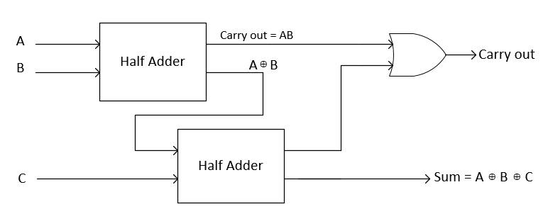
Bottom-Up Methodology Design and simulate Full-Adder using 2 Half-Adder and or gate .

Bottom-Up Methodology Design and simulate Full-Adder using 2 Half-Adder and or gate .
Example-2: Design a full adder by using two half adder.
Truth table is given below:

By observing truth table for full adder we can deduce its output boolean expression given below:

 Sum ===ABC+ABC+ABC+ABCA(BC+BC)+A(BC+BC)=A(BC)+A(BC¯¯¯¯¯¯¯¯¯¯¯¯¯)ABC  Carry ===ABC+ABC+ABC+ABCC(AB+AB)+AB(C+C)C(AB)+AB
As we can clearly see from boolean expressions that full adder can be constructed by using two half adders. A block diagram for this is shown below:
By using hierarchical style coding we can construct full adder using two half adder as shown in the block diagram above
Verilog Code:
1
2
3
4
5
6
7
8
module full_adder_join(fsum, fcarry_out, a, b, c); 
 input a, b, c; 
 output fsum, fcarry_out; 
 wire half_sum_1, half_carry_1, half_carry_2; 
 
 half_adder HA1(half_sum_1, half_carry_1, a, b); //instance 1 of Half Adder
 half_adder HA2(fsum, half_carry_2, half_sum_1, c); //instance 2 of Half Adder
 or or1(fcarry_out, half_carry_2, half_carry_1); 
endmodule


module half_adder(sum, hcarry, a, b); 
 input a, b; 
 output sum, hcarry; 

 xor sum1(sum, a, b); 
 and carry1(hcarry, a, b); 
endmodule

where half adders code are already mentioned in Example-1. Note that we have called half adder 2 times as shown in block diagram as well. This will create two instance of the same module.
Test Bench Code:
1
2
3
4
5
6
7
8
9
10
11
12
13
14
15
16
17
18
19
20
21
22
23
24
25
26
27
28
29
30
31
32
33
34
35
36
37
38
39
40
`timescale 100ns / 10ns 

module full_adder_2_HA_tb; 
 wire t_out_sum, t_out_carry; 
 reg t_a, t_b, t_c; 
 full_adder_join UUT(.a(t_a), .b(t_b), .c(t_c), .fsum(t_out_sum), .fcarry_out(t_out_carry)); 
initial 
begin // 1 
 t_a = 1'b0; t_b = 1'b0; t_c = 1'b0;
 #20 //2 
 t_a = 1'b0; t_b = 1'b0; t_c = 1'b1;
 #20 //3 
 t_a = 1'b0; t_b = 1'b1; t_c = 1'b0;
 #20 //4 
 t_a = 1'b0; t_b = 1'b1; t_c = 1'b1;

 #20 //5 
 t_a = 1'b1; t_b = 1'b0; t_c = 1'b0;
 #20 //6 
 t_a = 1'b1; t_b = 1'b0; t_c = 1'b1;
 #20 //7 
 t_a = 1'b1; t_b = 1'b1; t_c = 1'b0;

 #20 //8
 t_a = 1'b1; t_b = 1'b1; t_c = 1'b1;
end 
initial 
begin 
 #180 $stop;
end

endmodule
The above code is simulated in Modelsim and below are the simulated result:


The above result shows the correct working of the Full adder as provided in the truth table.
These two examples are the basic guidelines on how to write code in a hierarchical style.


2024_09 作業3 以Node-Red 為主

 2024_09 作業3  (以Node-Red 為主  Arduino 可能需要配合修改 ) Arduino 可能需要修改的部分 1)mqtt broker  2) 主題Topic (發行 接收) 3) WIFI ssid , password const char br...